
 EN

Climb onto the fan deck of an induced-draft cooling tower at a Sinopec petrochemical unit or a Linglong Tire utility plant in August, and the mechanical weak points are obvious. A high-speed motor sits outside the airstream, spinning a two-meter floating jackshaft through flexible disc couplings into a right-angle bevel gearbox soaked in warm vapor. Every time condenser water temperature shifts and the controller ramps fan speed up or down, torsional shock ripples through keys, couplings, and gear teeth until metal fatigue or water-contaminated oil forces a crane shutdown.
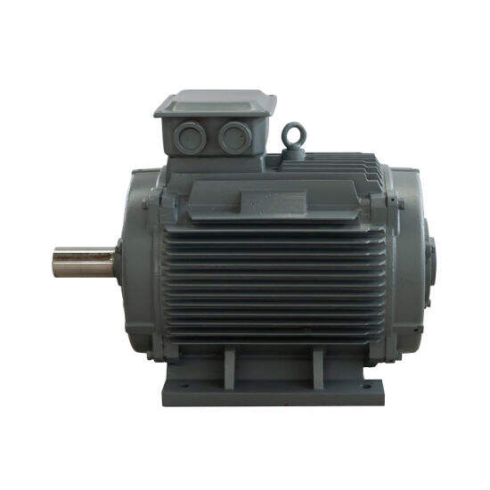
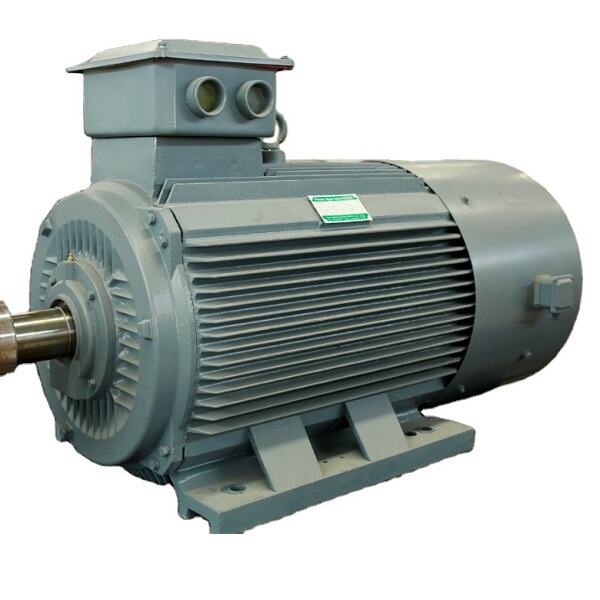
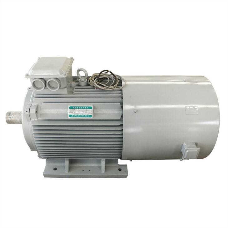
Replacing that multi-piece chain with a cooling tower direct drive motor puts a low-speed, high-torque permanent magnet rotor right under the fan hub. ENNENG engineers these sealed permanent magnet machines across a unified 5kW-5MW power range and 110V-690V voltage range, alongside 1kW-10kW vertical axis wind turbine generators (3kW, 5kW, and 10kW units). By cutting out the right-angle reducer and long driveshaft, a Cooling Tower Direct Drive layout removes the exact mechanical joints where cyclic bending and torsional fatigue accumulate.
Why Cyclic Fan Modulation Beats Up Conventional Gear Trains
Continuous availability on a cooling tower rarely means steady load. Wet-bulb temperatures swing between day and night, process heat loads shift, and Variable Frequency Drives (VFDs) constantly trim fan RPM.
Torsional Backlash, Jackshaft Whip, and Wet-Deck Corrosion
In a geared fan cell, every speed ramp or restart sends a torque wave down the composite or steel driveshaft. Even slight angular misalignment between the external motor and the center gearbox flexes the coupling pack once per revolution. Over an 8,000-hour season at 1,500 RPM, fretting fatigue cracks coupling discs and hammers pinion bearings. Worse yet, when a fan slows down and speeds back up, gear-mesh backlash lets high-inertia blades coast and slap against pinion teeth. Switching to a cooling tower direct drive motor eliminates that intermediate spring-mass system.
Shortening the Load Path With High-Pole-Count PM Design
Instead of spinning at 1,500 RPM and stepping speed down through bevel gears, an ENNENG Gearless Motor packs a high number of NdFeB (Neodymium Iron Boron) permanent magnet poles onto the rotor so the shaft turns natively at fan speed—typically 80 to 220 RPM. The fan hub mounts straight onto the Direct Drive Motor shaft:
• Zero Gear-Tooth Contact Fatigue: With no bevel gear mesh in the airstream, pitting, spalling, oil leaks, and seasonal oil changes disappear from the schedule.
• No Floating Shaft or Guarding Work: Dropping the jackshaft and couplings eliminates alignment drift and simplifies OSHA 1910.219 shaft guarding on the deck.
• Focused Vibration Checks: If a blade picks up scale, technicians check fan balance and mounting bolts under ISO 10816 and ISO 20816 limits instead of isolating couplings and pinions.
|
Tower Drivetrain Factor |
ENNENG Cooling Tower Direct Drive |
Conventional Motor + Shaft + Gearbox |
|
Torque Path |
Direct Drive Motor coupled to fan hub |
High-speed motor + jackshaft + reducer |
|
Cyclic Fatigue Points |
Single rotor-to-hub joint; zero backlash |
Coupling flex, keyway wear, gear slap |
|
Thermal & Rotor Loss |
Zero rotor copper loss; 20K cooler (<60K) |
Induced rotor heat + oil churning loss |
|
Part-Load Efficiency |
IE5 (IEC 60034-30-1); flat 25%-120%; PF 0.95-1.0 |
Efficiency drops when VFD trims speed |
|
Power & Voltage |
5kW-5MW / 110V-690V (Wind: 1kW-10kW; 3kW, 5kW, 10kW) |
Bulky frames + external oil breathers |
Thermal Endurance and VFD Tuning Under Long Cyclic Runs
Getting rid of the gearbox solves mechanical transmission fatigue, but thermal and electrical stress inside a humid fan stack still require careful engineering.
1. Running 20K Cooler Across Partial-Load Fan Curves
Because fan power follows the cube of speed, a cooling tower fan at 60% speed pulls less than a quarter of full-load kilowatts. Standard induction motors lose efficiency and power factor rapidly below 50% load. An ENNENG cooling tower direct drive motor holds a flat IEC 60034-30-1 IE5 efficiency plateau from 25% to 120% load (+2% to 5% higher rated efficiency) and a 0.95 to 1.0 power factor, trimming line current by over 10%. Because the permanent magnet rotor draws zero excitation current, rotor copper loss is zero and winding temperature rise stays 20K lower than induction units (under 60K). Under IEC 60034-1 cyclic duty, running 20K cooler slows insulation aging and stops condensation breathing. Across retrofits at Shandong Gold Mine, Linglong Tire, and Sinopec, ENNENG drives cut machinery power draw by 7% to 40% and variable-flow electricity by up to 50%.
2. Programming VFD Ramps and Skip Frequencies to Stop Blade Resonance
Mounting a Cooling Tower Direct Drive unit directly under multi-meter FRP fan blades means the VFD must act as a damper. Abrupt current steps flex blade roots. Commissioning crews should program smooth S-curve ramps and lock out resonant RPM bands using VFD skip-frequency settings. To protect stator coils against pulse-width modulated (PWM) voltage spikes over long tower cables, windings must meet ANSI/NEMA MG 1 Part 31 dielectric rules and NFPA 70 grounding codes, while holding noise below 55 dB.
Field Commissioning Checklist for Tower Retrofits
Supported by specialists from the National Rare Earth Permanent Magnet Engineering Centre and dozens of patents, ENNENG customizes each cooling tower direct drive motor and Direct Drive Motor across 110V-690V (380V/660V/1140V) and 6kV/10kV ratings—built one to two frame sizes smaller to reduce airflow blockage. Before seasonal service, crews should verify three details:
• Hub Concentricity & Pitch: Check bushing runout, torque bolts, and verify blade pitch angles so imbalance does not side-load Gearless Motor bearings.
• Moisture Sealing: Confirm IP65 labyrinth seals, sealed terminal boxes, and anti-condensation heaters for humid plume exposure.
• Scheduled Care: Grease insulated bearings on schedule and wash scale off cooling fins during basin cleanouts to hold <60K temperature rise.
Talk with ENNENG Engineering
Connect with the ENNENG engineering support team with fan diameter and target RPM data to get a tailored cooling tower direct drive motor proposal:
- WhatsApp: +86 18562780228
- E-Mail: [email protected]
- Phone: +86 532 66000559
FAQ
Q: How does a cooling tower direct drive motor prevent mechanical fatigue compared to a geared fan drive?
A: A cooling tower direct drive motor couples the fan hub directly to a low-speed permanent magnet rotor, eliminating the right-angle bevel gearbox, long floating jackshaft, and flexible couplings. Removing these intermediate components stops gear-tooth pitting, coupling fretting, keyway wear, and oil-water emulsification during frequent seasonal speed changes, keeping vibration within ISO 20816 limits.
Q: Why does a Cooling Tower Direct Drive system save more electricity during night and winter shifts?
A: When ambient temperatures drop, VFDs slow cooling tower fans down to partial load where standard induction motors suffer steep efficiency and power factor losses. An ENNENG Cooling Tower Direct Drive holds IE5 efficiency across 25% to 120% load and a 0.95 to 1.0 power factor, cutting line current by over 10% and running 20K cooler.
Q: What power, voltage, and protection options can ENNENG customize for wet cooling tower decks?
A: ENNENG customizes each Direct Drive Motor and industrial generator across a unified 5kW-5MW power range and 110V-690V operating voltage range, alongside 1kW-10kW vertical axis wind turbine generators focused on 3kW, 5kW, and 10kW units. Tower motors feature IP65 moisture protection, corrosion-resistant coatings, and ANSI/NEMA MG 1 Part 31 inverter-duty winding insulation.

