
how-cooling-tower-direct-drive-motor-improves-system-uptime-of-industrial-cooling-tower-facilities, how-cooling-tower-direct-drive-motor-improves-system-uptime-of-industrial-cooling-tower-facilities, /blog
EN

2026/10/09
Industrial manufacturing plants, chemical processing facilities, and power stations depend on continuous cooling water circulation to sustain stable thermodynamic processes. In a synthetic rubber manufacturing facility operating eight heavy-duty crossflow cooling tower cells, recurring mechanical drivetrain failures produced repeated summer emergency shutdowns. Diagnostic analysis revealed that high-speed driveshaft couplings failed under aerodynamic cyclic vibration, while right-angle gearboxes suffered catastrophic bearing destruction due to emulsified lubrication oil. Upgrading cooling cells to an advanced Cooling Tower Direct Drive architecture eliminated mechanical gearboxes and intermediate couplings entirely, immediately restoring continuous plant uptime. Industrial operations cannot afford cooling water interruptions that force process throttling and multimillion-dollar production losses.
|
Drivetrain Component |
Failure Mechanism |
Operational Impact |
Direct Drive Solution |
|
Intermediate Driveshaft |
Flexible coupling shear / fatigue |
Severe vibration trip, fan stack rupture |
Eliminated (Direct rotor mount) |
|
Right-Angle Gearbox |
Seal leaks, oil emulsification |
Bearing seizure, gear tooth stripping |
Eliminated (Zero gear lubrication) |
|
High-Speed Induction Motor |
Bearing current fluting, moisture ingress |
Insulation dielectric breakdown |
IP66/IP68 PM direct-drive unit |
|
External Belt / Pulley |
Belt elongation, pulley wear |
Airflow loss, continuous retensioning |
Eliminated (Permanent shaft lock) |
Traditional cooling tower mechanical drive trains are notoriously vulnerable because they operate inside hostile, moisture-saturated airstreams. Standard mechanical systems mount an induction motor outside or inside the fan stack, routing mechanical torque through extended floating driveshafts, intermediate pillow block bearings, and oil-filled gearboxes mounted directly below the fan hub. The hot, humid, and chemically treated airflow rapidly deteriorates mechanical seals, causing synthetic gear oil to wash away and moisture to corrode bearing races. Upgrading to a Cooling Tower Direct Drive motor eliminates these mechanical components, delivering unprecedented operational uptime.
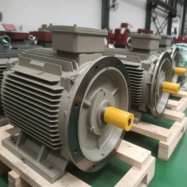
Long floating driveshafts require precise laser alignment between the motor and gearbox input shaft. However, fiberglass and wooden cooling tower decks expand, warp, and vibrate under variable thermal conditions and changing wind loads. Structural shifts misalign driveshafts, generating severe 2x rotational vibration harmonics that tear flexible rubber couplings apart. A Cooling Tower Direct Drive motor mounts directly beneath the fan impeller, completely removing intermediate driveshafts, dynamic couplings, and alignment headaches.
Right-angle cooling tower gearboxes hold between twenty and sixty liters of synthetic lubricating oil. Moisture routinely bypasses input and output shaft lip seals, emulsifying the lubricant into an abrasive sludge that destroys gear teeth within months. Furthermore, oil leaking down fan hubs contaminates the recirculating cooling water, fouling heat exchanger tubes throughout the factory. Transitioning to a Cooling Tower Direct Drive eliminates liquid gear oil entirely, safeguarding process water chemistry and eradicating periodic oil flush procedures.
Gear tooth meshing dynamics generate loud, high-frequency acoustic whining that propagates across plant boundaries and violates local community noise ordinances. Direct-drive permanent magnet synchronous motors operate at low rotational speeds without gear mesh friction, producing exceptionally smooth electromagnetic torque. Deploying a Cooling Tower Direct Drive routinely lowers fan cell sound pressure levels by 8 to 12 dBA, simplifying municipal environmental noise compliance.
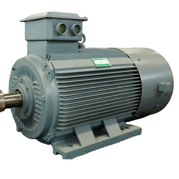
Maximizing cooling tower reliability requires electrical machinery engineered to operate continuously in saturated, corrosive environments. ENNENG manufactures advanced low-speed, high-torque permanent magnet direct-drive synchronous motors specifically optimized for cooling tower operations. Installing an ENNENG Cooling Tower Direct Drive boosts system operating efficiency up to 96 percent while dramatically improving facility availability.
|
Reliability Factor |
Geared Induction System |
ENNENG Cooling Tower Direct Drive |
|
Mechanical Transmission Losses |
12% — 22% Total Loss |
Zero Transmission Loss |
|
Lubrication Maintenance Demand |
2 to 4 Flushes / Year |
Zero Lubrication Changes |
|
Ingress Protection Rating |
IP54 — IP55 Standard Base |
IP66 to IP68 Hermetically Sealed |
|
Operating Voltage Versatility |
380V — 460V Rigid |
110V to 690V Unified Versatility |
ENNENG cooling tower platforms span adaptable operating voltages from 110V to 690V, integrating seamlessly with dedicated variable frequency control cabinets. Utilizing high-grade neodymium iron boron magnets, ENNENG direct-drive motors develop high starting and running torque, allowing direct shaft mounting of large composite fan impellers.
Operating within continuous 100 percent relative humidity demands superior sealing architecture. ENNENG direct-drive motors feature cast iron casings treated with marine-grade epoxy coatings. Terminal boxes incorporate dual-O-ring seals and potted cable gland entries. Rotor shafts are protected by dual non-contact labyrinth bearing isolators, preventing moisture and chemical aerosols from reaching internal bearing cavities.
Cooling water thermal rejection requirements vary dramatically between hot daytime peaks and cool nighttime operations. Standard single-speed induction motors run fans at full speed continuously or cycle motors abruptly on and off, inducing mechanical fatigue. An ENNENG Cooling Tower Direct Drive paired with a smart inverter modulates fan speeds continuously across seasonal weather shifts, capturing exponential energy savings while stabilizing cold-water basin temperatures.
Cooling tower equipment must adhere to rigorous international industrial standards governing thermal efficiency, electrical safety, and mechanical vibration. Thermal performance evaluation and aerodynamic ratings are governed by Cooling Technology Institute (CTI) STD-201 and CTI ATC-105 verification codes.
Mechanical vibration thresholds for cooling tower fan assemblies are defined under ISO 10816-3 and ISO 20816-3. A direct-drive Cooling Tower Direct Drive motor easily complies with Zone A vibration limits, keeping vibration velocities well below 1.4 mm/s RMS across operating speed ranges. Electrical safety, overcurrent protection, and motor branch circuit grounding must satisfy NFPA 70 National Electrical Code rules. Furthermore, OSHA 1910 Subpart O regulations highlight the safety benefits of eliminating high-speed rotating mechanical driveshafts, removing dangerous entanglement risks for maintenance personnel servicing fan decks.
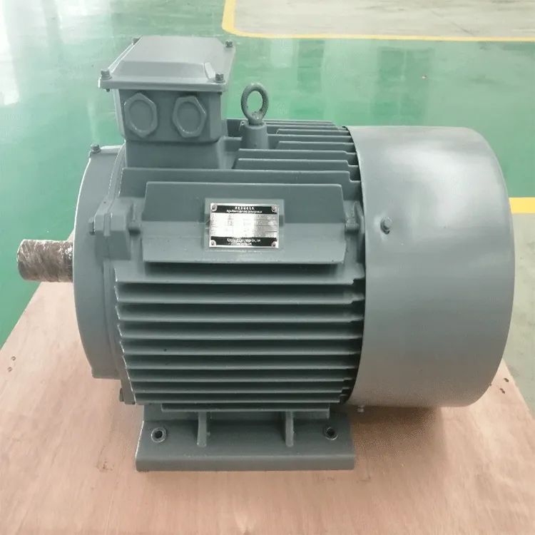
Executing a successful cooling tower retrofit requires disciplined mechanical assessment and structured installation practices.
Before removing legacy geared hardware, inspect the structural steel beams inside the cooling tower plenum. High-torque direct-drive motors concentrate total motor and fan weight directly onto the central support beam. Verify that structural beam deflection remains under 1.0 mm under full dynamic aerodynamic thrust, preventing fan blade tip clipping against the fan cylinder shroud.
Because permanent magnet direct-drive motors operate through variable frequency drives, install shielded symmetrical inverter-duty power cables between the motor control center and the cooling tower stack. Select drive controllers featuring built-in anti-windmilling algorithms to arrest reverse-spinning fan blades softly before accelerating forward, protecting mechanical fan blades from rotational shock.
Direct-drive cooling systems reduce maintenance overhead to minimal periodic checks. Technicians only need to verify electrical terminal torque annually, conduct external housing thermal scans, and monitor bearing vibration signatures using permanently mounted accelerometers. Lubricant flushes, belt re-tensioning, and laser alignments are eliminated completely, maximizing industrial cooling uptime.
To explore direct-drive cooling motor models and dimensional drawings, visit the ENNENG Products Catalog and review solutions on the ENNENG Cooling Systems.
For technical inquiries and engineering support on cooling tower uptime modernization, contact ENNENG:
Q: How does a Cooling Tower Direct Drive handle reverse fan freewheeling?
A: When cooling cells are turned off, natural thermal draft or ambient winds can cause fan blades to freewheel in reverse. Attempting to start an induction motor during reverse freewheeling shears driveshafts and trips breakers. Modern variable frequency drives paired with a Cooling Tower Direct Drive utilize active DC-injection braking to hold the motor stationary before ramping smoothly forward.
Q: Can existing fan hubs be mounted onto a direct-drive motor shaft?
A: Yes. Direct-drive retrofit installations utilize precision-machined taper bushing adaptors engineered to match existing fan hub bores. The composite fan impeller, blade pitch angles, and aerodynamic characteristics remain unchanged, allowing industrial plants to reuse expensive composite fan assemblies without performance degradation.
Q: Why do direct-drive motors run cooler than geared induction systems?
A: Standard systems generate significant friction inside mechanical gear reducers and experience substantial I2R copper losses inside induction rotors. An advanced Cooling Tower Direct Drive eliminates gear mesh friction entirely and utilizes permanent magnet synchronous excitation, which produces negligible rotor heating. Operating with low temperature rise prolongs winding insulation and bearing grease life.


 EN