A multi-train petrochemical processing facility operates massive induced-draft cooling towers continuously to reject process heat from synthesis loops and distillation columns. Under these rigorous working conditions, the circulating water infrastructure constantly exposes driveline components to elevated humidity, chemical biocide mist, and fluctuating thermal cycles. Maintaining stable heat dissipation across continuous manufacturing processes requires mechanical fan equipment that operates dependably without frequent mechanical breakdowns.
Operating conventional cooling tower fan drivelines involves severe mechanical vulnerabilities. Traditional installations rely on high-speed induction motors coupled to intermediate drive shafts, flexible couplings, and right-angle reduction gearboxes. Lubricant breakdown inside elevated gearboxes frequently causes gear tooth pitting, dynamic seal failure, and oil contamination within circulating water streams. Drive belts also slip and stretch under humid draft conditions, lowering fan velocity and reducing heat rejection efficiency. To eliminate these chronic maintenance liabilities, ENNENG provides direct-drive permanent magnet synchronous motor systems that mount the fan directly onto the motor shaft, completely removing intermediate mechanical transmission elements.
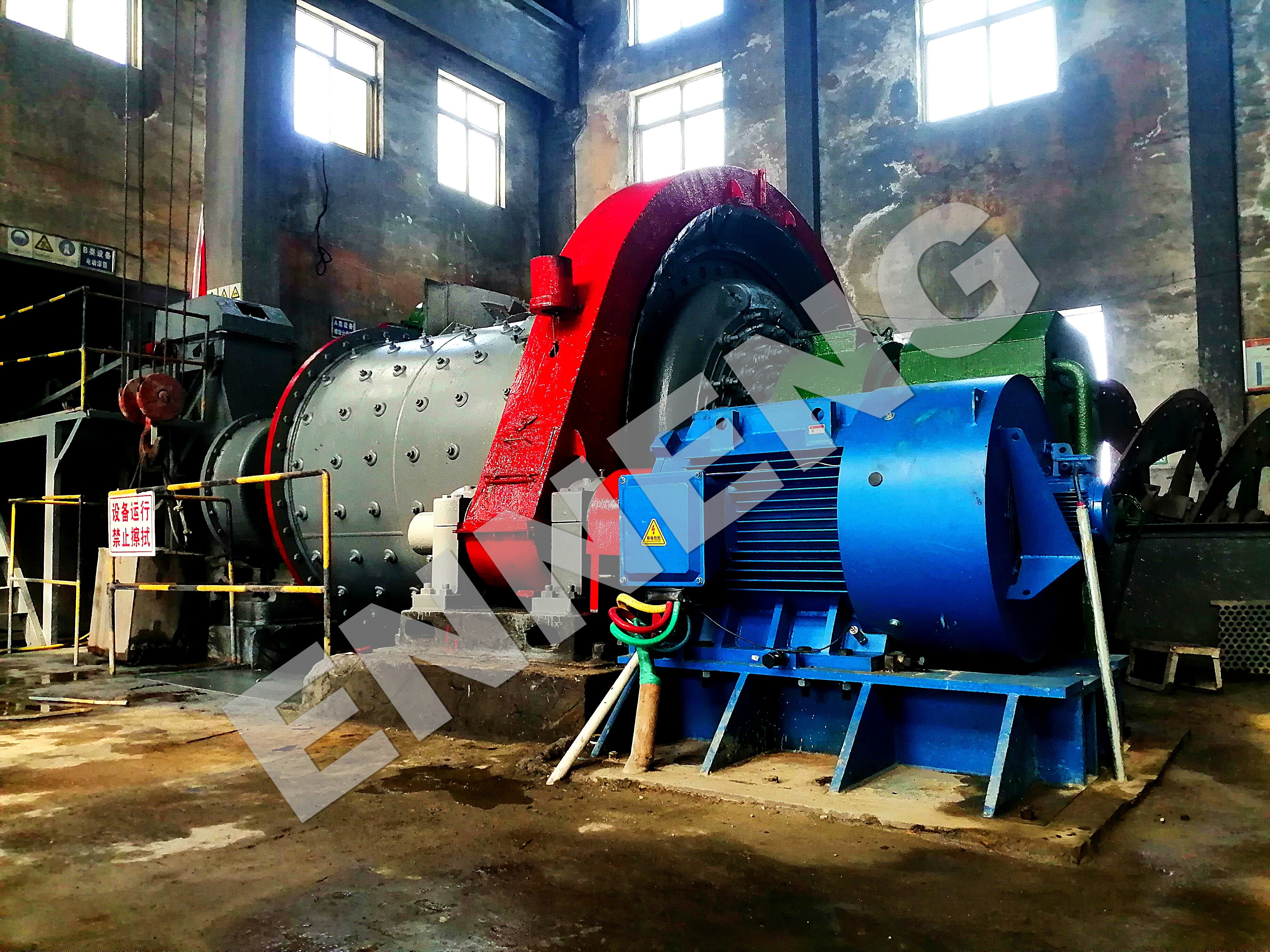
Operational Risks in Industrial Circulating Water Facilities
Mechanical Failures Inherent to Gearbox and Intermediate Drivelines
Right-angle speed reduction gearboxes operating in wet cooling towers experience continuous internal condensation and thermal expansion cycles. Gear oil must withstand water contamination, yet dynamic lip seals degrade rapidly when exposed to airborne biocides and suspended mineral drift. Water ingress emulsifies synthetic gear lubricants, leading to rapid abrasive wear and micro-pitting along bevel gear contact faces.
Intermediate drive shafts connecting remote motors to gear reducers present major mechanical risks. Thermal expansion across structural steel support beams causes angular and parallel misalignment between the motor shaft and the gearbox pinion shaft. This misalignment generates high-frequency vibrations that damage intermediate support bearings and fatigue flexible coupling elements. Inspecting or replacing these heavy mechanical components inside wet fan cowls poses serious safety hazards and operational difficulties.
Environmental Degradation and Process Downtime Hazards
Cooling tower fan cowls subject mechanical drive hardware to continuous environmental attack. Standard induction motor frames and steel belt enclosures trap moisture, encouraging heavy surface rust and galvanic corrosion. In belt-driven installations, rubber belts absorb moisture and chemical vapors, leading to rapid belt elongation, pulley groove polishing, and unexpected belt separation during peak operating periods.
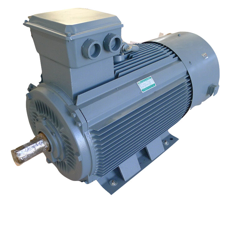
Engineering Advantages of Cooling Tower Direct Drive Systems
Mechanical Architecture and Total Transmission Elimination
A Cooling Tower Direct Drive configuration fundamentally alters mechanical fan power transmission. The low-speed, high-torque permanent magnet motor connects directly to the fan hub via a rigid flange interface. By dispensing with gearboxes, intermediate drive shafts, dynamic gear seals, and transmission belts, the Cooling Tower Direct Drive architecture removes up to seventy percent of moving components found in traditional drive trains.
Industrial circulating water facilities utilizing a Cooling Tower Direct Drive system achieve direct electromechanical coupling. The motor rotor utilizes high-grade rare-earth permanent magnets that generate synchronous magnetic flux without slip losses. Because fan rotational speed matches rotor velocity precisely, operators achieve smooth, low-vibration power transfer directly at the fan blades.
|
Feature
|
Conventional Gearbox / Belt Drive
|
Cooling Tower Direct Drive
|
|
Transmission Elements
|
Drive shaft, couplings, gearbox
|
Direct flange coupling to fan hub
|
|
Mechanical Transmission Loss
|
5% to 12% total power loss
|
< 0.5% (virtually zero loss)
|
|
Lubrication Requirements
|
Periodic oil changes & seal checks
|
Sealed long-life bearing grease
|
|
Vibration Profile
|
Higher (multi-component harmonics)
|
Low structural vibration
|
|
Variable Speed Capability
|
Limited or mechanically stepped
|
Stepless 0-100% via VFD
|
|
Water Ingress Risk
|
High risk at dynamic oil seals
|
IP66/IP67 hermetic enclosure
|
High-Torque Electromagnetic Density and Variable Aerodynamic Control
The low-speed high-torque topology of permanent magnet motors delivers exceptional torque density across a broad speed range. Unlike squirrel-cage induction motors that require high rotational speeds to generate adequate shaft torque, permanent magnet synchronous designs sustain peak torque at low rotational speeds, typically between 80 and 250 RPM. This allows direct coupling to large-diameter axial fans without mechanical gear reduction.
Variable frequency drives (VFDs) modulate the Cooling Tower Direct Drive system to track thermal process loads in real time. During colder nocturnal hours or reduced production shifts, the Cooling Tower Direct Drive system throttles fan RPM dynamically. Operating at partial speeds drastically lowers aerodynamic drag and electrical consumption, while avoiding the mechanical resonant frequencies that plague gearbox installations.
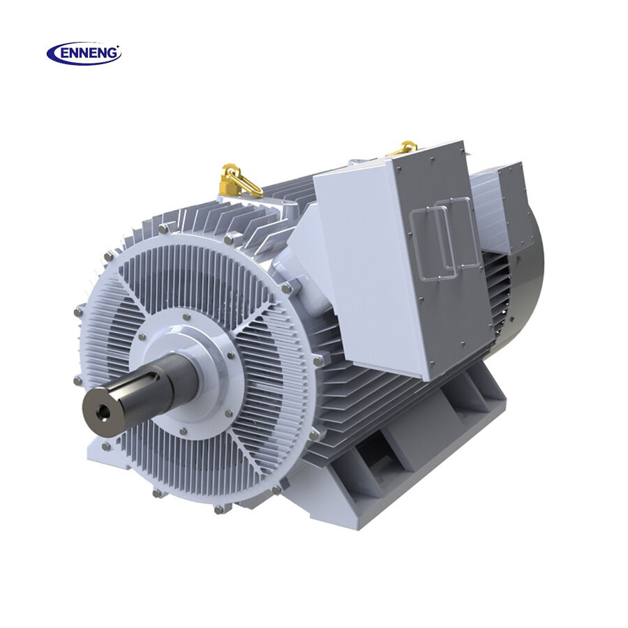
ENNENG Permanent Magnet Direct Drive Solutions
ENNENG manufactures industrial permanent magnet motors engineered specifically for wet circulating water environments. Available across power ratings from 5kW to 5MW with operational voltages between 110V and 690V, these machines feature IP66 or IP67 environmental sealing. Cast housings treated with multi-layer epoxy coatings resist acid drift, alkaline vapors, and constant water splashing.
ENNENG systems incorporate heavy-duty spherical roller and angular contact thrust bearings lubricated with specialized synthetic grease rated for over 50,000 continuous operating hours. Winding insulation systems meet Class H thermal standards with vacuum pressure impregnation (VPI), safeguarding copper conductors against dielectric breakdown caused by ambient humidity.
Compliance Standards and Industrial Safety Protocols
Vibration Severity Limits Under ISO 10816-3 and ISO 1940-1
Excessive vibration in cooling towers damages fan blades, cracks fiberglass fan stacks, and loosens structural framing bolts. ISO 10816-3 defines broadband vibration evaluation criteria for industrial machinery operating on support structures. Traditional gearbox assemblies often generate vibration velocities exceeding 4.5 mm/s RMS due to gear mesh excitation and shaft misalignments.
A Cooling Tower Direct Drive system maintains smooth rotation that typically registers below 1.5 mm/s RMS, remaining securely inside the ‘Good’ operating zone (Class A/B) of ISO 10816-3. Balancing standards conforming to ISO 1940-1 Grade G2.5 ensure that ENNENG permanent magnet rotors eliminate eccentric forces, preserving composite fan blade roots and extending structural service life across circulating water towers.
OSHA 1910 Guarding and Maintenance Safety Regulations
OSHA 29 CFR 1910.219 sets rigorous safety requirements for mechanical power-transmission apparatus, including revolving shafts, couplings, gears, and pulleys. Maintaining compliance in traditional towers demands complex mechanical guards, physical lockouts, and challenging confined-space entry procedures. Technicians often work on damp, elevated platforms to inspect drive belts or replenish toxic gearbox lubricants.
Adopting a Cooling Tower Direct Drive system removes high-speed exposed intermediate shafts and belts, substantially simplifying OSHA compliance. Eliminating seasonal oil drains eliminates oil spill hazards on wet walking surfaces. Confined-space entries into hazardous fan cylinders occur far less frequently, protecting plant technicians and reducing insurance liabilities.
Lifecycle Selection, Inspection, and Maintenance Guidelines
Equipment Selection and Electrical System Matching
Selecting the correct Cooling Tower Direct Drive unit involves calculating aerodynamic fan blade torque curves, structural cantilever loads, and ambient thermal variables. Motor power ratings within the standard 5kW to 5MW range must match peak airflow static pressure demands, while winding voltage selections (110V to 690V) must integrate cleanly with plant power distributions.
Engineers should verify that the associated variable frequency inverter provides suitable closed-loop vector or sensorless field-oriented control algorithms. Incorporating thermal sensors (PT100 or PTC thermistors) inside motor stator slots and bearing housings ensures continuous thermal telemetry to the distributed control system (DCS).
Practical Care and Electrical Protection Strategies
To maximize the operating lifespan of a Cooling Tower Direct Drive motor, install an inverter output sine-wave filter or dV/dt choke if the cable run from the electrical cabinet to the cooling tower exceeds 50 meters. This suppresses high-frequency voltage spikes that can degrade winding insulation. Additionally, grounding rings on the output shaft eliminate common-mode bearing currents, preventing electric discharge machining (EDM) fluting on bearing raceways.
Upgrading industrial circulating water facilities with reliable direct-drive solutions enhances process safety, reduces labor overhead, and stabilizes plant production. Learn how advanced permanent magnet drive systems can modernize facility operations by visiting ENNENG Contact Page to consult with application engineers.
FAQ
Q: What makes a Cooling Tower Direct Drive motor more reliable than conventional gearboxes?
A: A Cooling Tower Direct Drive motor eliminates critical failure points such as multi-stage reduction gears, flexible intermediate drive shafts, and dynamic oil seals. By coupling the fan directly to a low-speed permanent magnet synchronous motor, mechanical friction losses drop significantly. Eliminating gear oil prevents lubricant emulsification in humid tower environments, allowing industrial circulating water systems to operate continuously without frequent unscheduled driveline overhauls.
Q: How does cooling tower direct drive technology handle variable cooling loads?
A: Cooling tower direct drive technology operates synchronously with variable frequency drives, offering precise, stepless speed modulation from zero to full rated speed. Because permanent magnet motors maintain high efficiency and full torque output even at partial speeds, the system can reduce fan RPM during cooler ambient conditions. This dynamic adjustment matches heat rejection requirements accurately, cuts electrical consumption, and avoids mechanical drivetrain resonance.

 EN


