
 EN

How Direct Drive Motor Enhances Equipment Response Speed on Intelligent Automated Industrial Production Lines
On a fast automated line, a delayed axis is rarely caused by one part alone. Command processing, drive tuning, motor torque, load inertia, couplings, gearboxes, belts, sensors, and mechanics all contribute to the time between a motion request and a stable result. A Direct Drive Motor can improve that chain by applying torque to the load without a conventional gearbox, belt, or pulley stage. The benefit is not a magic speed number. It is a simpler mechanical path that gives the control system fewer elastic and backlash-prone elements to manage.
For engineers planning indexing tables, rotary transfer stations, inspection axes, winding equipment, or coordinated robot cells, the practical question is: where is response being lost today? This article explains how a Direct Drive Motor changes the response budget, which design checks still matter, and how to validate the result on an intelligent production line.
Response speed is a system behavior, not a catalog value
Equipment response speed may mean rapid acceleration, shorter settling time, quicker reversal, better tracking of a changing command, or faster recovery after a disturbance. These measures are related but not identical. A motor with high peak torque can still produce a disappointing move if the mechanism twists, a reducer adds compliance, the encoder resolution is insufficient, or the servo loop is tuned too conservatively.
A useful review starts by separating the motion chain into five layers:
- Command layer: PLC, motion controller, interpolation, network update rate, and synchronization logic.
- Drive layer: current, speed, and position loops; limits; filtering; and fault handling.
- Motor layer: torque production, thermal capability, rotor inertia, and feedback interface.
- Transmission layer: gearbox, belt, coupling, pulley, or other components between motor and load.
- Load layer: payload inertia, friction, imbalance, structural stiffness, resonance, and process contact forces.
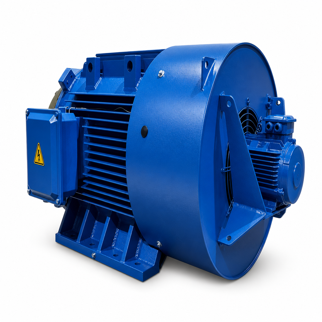
Why fewer mechanical interfaces can improve response
1. Less backlash during reversals and indexing
In a geared or belt-driven axis, a direction change can first take up clearance or deform compliant parts before the load responds. A Direct Drive Motor removes one or more interfaces where that lost motion can occur, provided the bearing arrangement and machine frame are also stiff enough.
2. A more direct feedback-to-load relationship
Servo systems use feedback to compare actual and commanded motion. When a motor encoder sits upstream of a flexible transmission, the controller can see motor position while the load lags or oscillates. A direct architecture reduces this separation. That does not eliminate the need for high-quality feedback or thoughtful tuning, but it can make the control loop more transparent. For critical process axes, a load-side encoder can still be valuable when structural compliance remains significant.
3. Better use of low-speed torque
Many production-line applications need controlled torque at low speed rather than extreme shaft rpm. A torque-capable Direct Drive Motor can be selected around the actual load requirement instead of relying on a reduction stage to multiply speed into torque. This can be helpful for large-diameter rotary tables, tension-sensitive web handling, slow inspection rotation, and synchronized material movement. The selection must account for continuous torque, peak torque, duty cycle, cooling, and the inertia reflected at the shaft.
4. Fewer wear points that can drift over time
Mechanical transmission components may introduce lubrication needs, belt tension changes, gear wear, or alignment sensitivity. These are maintenance concerns first, but they can become response concerns when their condition changes. A Direct Drive Motor cannot prevent every mechanical problem, yet reducing intermediate parts can make long-term dynamic behavior more repeatable and simplify root-cause work when cycle time begins to drift.
Where a Gearless Motor approach is most useful
A Gearless Motor approach is worth evaluating when the process requires frequent reversals, accurate low-speed positioning, compact motion architecture, or coordinated axes that must settle before the next operation starts. Typical candidates include electronic assembly tables, automated test fixtures, packaging indexing systems, semiconductor-support equipment, printing and converting modules, and automated inspection stations.
However, gearless does not automatically mean better for every machine. A reduction stage can still be appropriate when it matches a high-speed motor to a heavy load economically, protects the motor from an unsuitable inertia ratio, or supports a required form factor. The engineering objective is not to remove gears by default. It is to choose the transmission architecture that meets response, thermal, accuracy, service, and cost requirements together.
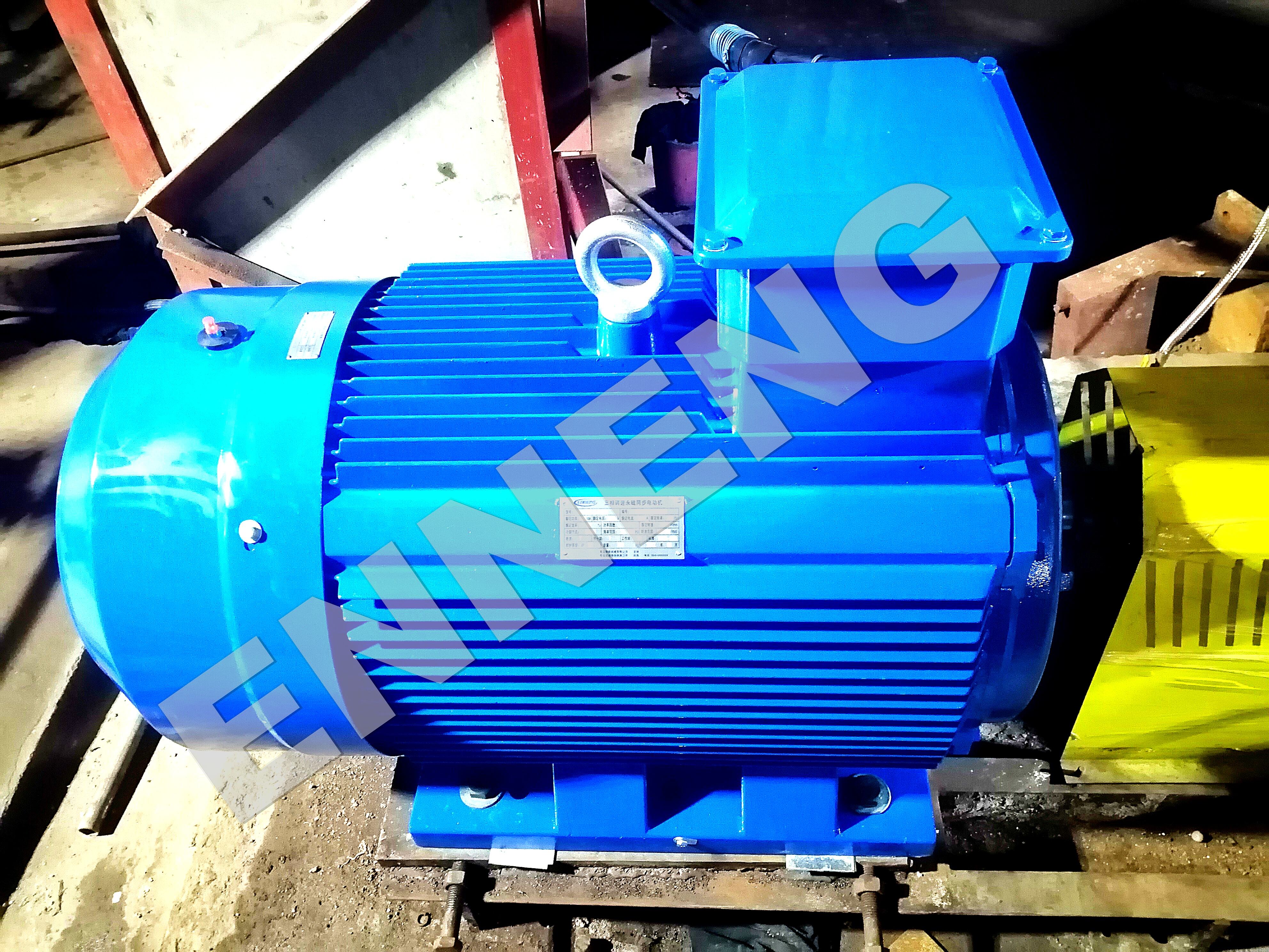
How to assess the response-speed opportunity
Before specifying a Direct Drive Motor, capture a baseline from the existing machine. Use time-stamped motion traces rather than operator impressions. Record command position, actual position, speed, torque or current, following error, settling time, and relevant process signals. Then review the following questions.
- What is the limiting event? Identify whether the bottleneck is acceleration, settle, sensor confirmation, network delay, mechanical vibration, or the process itself.
- What load inertia reaches the motor? Calculate or measure the load inertia at the axis and include fixtures, product variation, and rotating tooling.
- Which resonances are excited? A stiff-looking assembly can still have resonant modes. A direct connection can expose those modes because the motor is more closely coupled to the load.
- What torque is needed across the cycle? Check peak acceleration torque, continuous process torque, friction, gravity effects, and a realistic thermal duty cycle.
- How will feedback be implemented? Encoder resolution, mounting accuracy, cable routing, and drive compatibility affect how much response improvement is usable.
This approach prevents a common mistake: replacing a gearbox with a Direct Drive Motor while leaving the real response limitation—such as a flexible fixture or delayed inspection trigger—untouched.
Integrating direct drive into an intelligent production line
Intelligent automation benefits when motion data is useful as well as fast. During integration, connect the Direct Drive Motor design to the line’s diagnostic plan. Establish reference traces for a healthy move, define alarms for abnormal following error or torque demand, and keep setup parameters under revision control. Where synchronized axes share a network, verify cycle timing, clock synchronization, and fault-recovery behavior before claiming a throughput gain.
Safety also belongs in the architecture review. Variable-speed drive safety functions are addressed in standards such as IEC 61800-5-2, but the required functions and validation depend on the full machine risk assessment. A motor choice alone is not evidence of compliance. Coordinate the motor, drive, safety control, braking or holding method, and restart sequence with the machine-safety team.
For OEMs and system builders, early collaboration with a permanent-magnet motor manufacturer can help align torque-speed requirements, mounting envelope, feedback needs, cooling assumptions, and integration constraints. Qingdao Enneng Motor CO., Ltd. provides PMSM motor solutions for industrial applications; the final configuration should be validated against the actual load profile and machine test data.
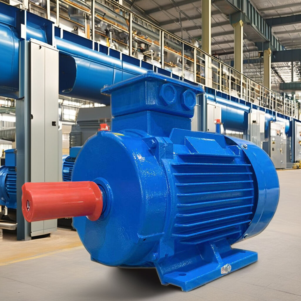
A commissioning method that proves the gain
Commissioning should demonstrate response at the load, not merely at the motor shaft. Start with conservative current and speed limits, verify rotation and feedback polarity, then tune the loops in stages. Run an unloaded profile, a representative production profile, and a worst-case payload or temperature condition. Compare the direct-drive axis with the baseline using the same command profile.
- Measure acceleration time, peak following error, settling time, and final positioning repeatability.
- Inspect torque/current traces for unexpected friction, imbalance, or resonance.
- Check process quality: registration, placement, tension, cut position, or inspection stability.
- Confirm that thermal behavior remains acceptable across the real operating duty.
- Document parameter changes so maintenance teams can restore a proven state.
If the new axis settles faster but causes frame vibration, reduce the tuning target or improve structural stiffness. If it accelerates well but overheats, revisit continuous torque and cooling assumptions. A stable operating window matters more than an aggressive gain setting seen in a brief demonstration.
Contact US
If you are evaluating commercial permanent magnet motors for sale and need an engineered drive solution that guarantees efficiency and longevity, ENNENG is your trusted partner.Contact ENNENG Today.Speak to our technical engineering team to receive a customised drive proposal.
- WhatsApp: +86 18562780228
- E-Mail: [email protected]
- Phone: +86 532 66000559
Putting direct drive into practice
A Direct Drive Motor can enhance response speed on an intelligent automated industrial production line by removing intermediate transmission behavior that consumes motion accuracy and tuning margin. Its strongest contribution is mechanical clarity: less backlash, a shorter torque path, and a feedback relationship that can better reflect load behavior. A Gearless Motor architecture still requires disciplined inertia analysis, resonance control, servo tuning, thermal design, safety review, and measured commissioning. When those pieces are engineered together, direct drive becomes a practical way to turn quicker commands into quicker, more repeatable machine response.

