Original equipment manufacturers (OEMs) designing high-performance industrial machinery face a continuous challenge: delivering higher dynamic positioning precision, faster cycle speeds, and greater structural reliability while minimizing total machine footprint and build cost. In conventional machine architecture—including rotary indexing carousels, metal-forming presses, heavy material handling conveyors, and plastic extruders—the drivetrain relies on a chain of mechanical intermediaries. Designers must incorporate high-speed motors, planetary gear reducers, timing belts, pulleys, and flexible shaft couplings. This multi-element transmission strategy introduces mechanical compliance, assembly stack-up errors, and maintenance vulnerabilities. Transitioning to a Direct Drive Motor architecture allows equipment builders to eliminate intermediate mechanical stages, radically streamlining machine layout.
Mechanical Transmission Liabilities in Conventional Machinery
Tolerance Stack-Up, Backlash, and Dynamic Lag: When mechanical engineers connect an electric motor to a working machine spindle through gearboxes and shaft couplings, every mechanical interface introduces positional inaccuracy. Gear teeth require mechanical backlash to operate without binding, introducing angular play that accumulates across multi-stage reducers. In high-speed indexing or precision positioning applications, this backlash degrades repeat accuracy and causes hunting oscillations during servo settling. Furthermore, mechanical transmission components exhibit structural torsional elasticity. Under sudden acceleration or heavy load changes, drive shafts and timing belts act as torsional springs, introducing dynamic lag, ringing vibration, and position errors that limit production throughput.
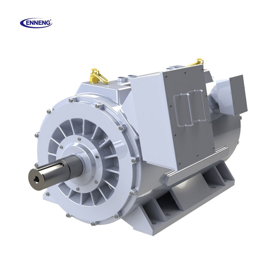
Structural Bulk, Part Counts, and Procurement Lead Times: The spatial volume demanded by conventional drivetrains imposes severe constraints on overall machine design. Intermediate gear reducers, adapter flanges, motor brackets, and protective belt guards consume valuable machine floor space and increase total equipment mass. Machine builders must manage dozens of individual part numbers, each requiring precision machining, inventory stocking, and manual assembly. Sourcing specialized precision planetary or worm gear reducers often involves lead times exceeding 20 weeks, creating supply chain bottlenecks that delay commercial machine deliveries. To resolve these engineering and logistical constraints, ENNENG supplies high-torque Direct Drive Motor solutions across the 5kW to 5MW power spectrum and 110V to 690V operating ranges, enabling machinery OEMs to mount motor rotors directly to machine drive shafts.
Mechanical Simplification Mechanisms of Direct-Drive Motor Architecture
Direct Rotor Coupling and Zero-Backlash Transmission: A Direct Drive Motor eliminates all intermediate transmission elements by coupling the motor rotor directly to the driven machine shaft. By utilizing high-density permanent magnet topologies, an ENNENG direct-drive motor delivers extreme continuous torque at low rotational speeds, matching the exact speed-torque profile required by the machine process without needing a speed-reducing gearbox. Because the load is directly locked to the electromagnetic field of the rotor, mechanical backlash is reduced to zero. Dynamic torsional stiffness increases by an order of magnitude, enabling higher servo control loop gains, faster settling times, and superior dynamic contouring accuracy in automated machinery.
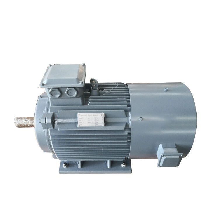
Spatial Integration, Hollow-Shaft Architectures, and Part Consolidation: Direct drive motors allow mechanical designers to transform the electric motor from an awkward external appendage into an integrated structural element of the machine. ENNENG offers customized direct-drive packages featuring large-diameter hollow through-bore shafts, bespoke mounting flanges, and integrated cartridge bearing housings. A hollow-shaft direct drive motor allows pneumatic lines, hydraulic piping, electrical cables, or laser optics to pass straight through the center of the drive axis, eliminating external cable tracks and reducing machine footprint. Equipment builders consolidate dozens of mechanical parts into a single compact motor assembly, cutting factory assembly hours and eliminating mechanical alignment procedures.
Machinery Safety Standards and OEM Engineering Design Steps
Compliance With ISO 12100, IEC 60204-1, and ISO 1940-1 Standards: Integrating direct-drive technology into industrial machinery requires adherence to international safety and build standards. Machine design safety conforms to ISO 12100 principles, where eliminating high-speed rotating shafts, external belts, and exposed pinch points inherently enhances machine safety for operators. Electrical control integration adheres to IEC 60204-1 (Safety of Machinery - Electrical Equipment of Machines), ensuring proper overcurrent disconnection, thermal protection interlocks, and emergency stop coordination. Rotor dynamic balancing meets ISO 1940-1 Grade G2.5, preventing high-torque low-speed direct-drive assemblies from transmitting harmonic vibrations into sensitive machine tool bases.
Four-Phase OEM Drivetrain Simplification Protocol:
- Define Load Dynamics and Mass Inertia Ratios: Calculate continuous operating torque, peak acceleration torque, and load inertia to ensure an optimal direct-drive inertia matching ratio.
- Execute Spatial CAD Co-Design: Integrate 3D STEP models of the custom direct-drive motor housing into the machine chassis to optimize structural stiffness, mounting bolt access, and thermal dissipation paths.
- Configure Field-Oriented Drive Parameters: Commission the variable frequency drive using matched motor electrical constants (Rs, Ld, Lq, and back-EMF Ke), enabling high-bandwidth speed and position loops.
- Establish Preventative Maintenance Protocols: Direct-drive architectures eliminate gearbox oil changes, requiring only periodic bearing lubrication monitoring and electrical insulation checks at 1000V DC.
Contact Us
Simplifying equipment transmission architecture with direct-drive permanent magnet technology enables machinery manufacturers to build faster, more compact, and more reliable industrial systems. Engineering consultants at ENNENG partner with OEM mechanical design teams from initial kinematic modeling through prototype fabrication and volume series production. Contact our direct-drive application division to accelerate machine design programs:
FAQ
Q: How does a Direct Drive Motor eliminate mechanical backlash in production machinery?
A: A Direct Drive Motor connects its rotor directly to the driven machine spindle without intermediate gear teeth, pulleys, or couplings. Because there are no meshing mechanical interfaces, gear backlash is completely eliminated. Positioning precision is limited only by the resolution of the optical or magnetic feedback encoder, enabling sub-arcsecond positioning repeatability.
Q: Does eliminating the gearbox require oversizing the electric motor?
A: No, direct-drive motors are engineered specifically with high pole counts and dense permanent magnet arrays to produce very high continuous torque at low speeds. While the motor physical frame may be larger than a high-speed motor alone, the total physical footprint is significantly smaller than the combined envelope of a high-speed motor, mounting bell housing, flexible coupling, and multi-stage planetary gearbox.
Q: What machine applications benefit most from whole-machine transmission simplification?
A: Primary applications include rotary indexing carousels, machine tool rotary tables, industrial printing cylinders, wire drawing capstans, and heavy slurry pump skids. Any equipment where mechanical gearboxes suffer frequent backlash degradation, high maintenance costs, or severe physical space restrictions benefits immediately from direct-drive conversion.

 EN


