
 EN

When an industrial line stops because a reducer overheats, a coupling loosens, or a belt train drifts out of alignment, the motor is often blamed even when the fault began between the motor and the load. A Direct Drive Motor changes that fault path. Instead of routing torque through a gearbox, belt, chain, or multiple couplings, it applies torque directly to the driven axis.
That does not make a Direct Drive Motor failure-proof. It does, however, remove several wear-dependent parts from the transmission boundary and gives engineers a simpler system to inspect, monitor, and control. For applications with sustained low-speed torque demand, hard-to-access equipment, or costly unplanned downtime, that architectural change can materially reduce system failure exposure.
Why conventional transmission systems accumulate failure points
A geared transmission is a coordinated assembly rather than a single component. Gear meshes, bearings, shafts, seals, lubricant, housings, couplings, pulleys, and alignment all have to remain within acceptable operating conditions. Heat, vibration, contamination, overload, and installation error can interact: a bearing problem can disturb gear contact, worn teeth can create debris, and contaminated lubricant can accelerate further damage.
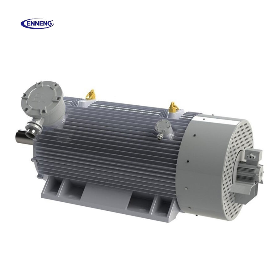
The key point is that these are system risks. A correctly selected motor may still be part of a troublesome line if the transmission introduces misalignment, lubrication dependence, or backlash that the process cannot tolerate. A Gearless Motor arrangement reduces the number of interfaces where those mechanisms can originate.
What a Direct Drive Motor removes from the risk chain
Direct drive describes the connection between motor and load, not a single motor technology. In a typical industrial implementation, a permanent-magnet motor is sized to deliver usable torque at the required speed and is connected directly to the driven machine. With no reduction stage, the design can eliminate or simplify several common maintenance concerns.
- Gear-mesh wear and tooth damage: there is no gearbox gear set to pit, scuff, fatigue, or require inspection.
- Lubricant-related faults: no gearbox oil circuit means no gearbox oil degradation, leakage, or contamination route to manage.
- Gearbox bearing and seal exposure: bearings and seals inside the removed reducer are no longer part of the system.
- Transmission alignment interfaces: fewer shafts, couplings, pulleys, and mounts can reduce opportunities for cumulative alignment error.
- Backlash-related process effects: removing gear reduction can improve the mechanical relationship between torque command and load response where precise positioning matters.
The benefit is not simply “fewer parts.” Fewer parts mean fewer condition-monitoring tasks, fewer spare-part categories, and fewer places where a small mechanical defect can propagate into vibration, heat, or an unplanned stop.
Failure-risk reduction starts with matching torque to the duty cycle
The most useful question is not whether direct drive is newer or more efficient in the abstract. It is whether the motor can supply the real torque-speed profile without asking a gearbox to create torque multiplication. That means examining continuous torque, peak and breakaway torque, acceleration, inertia, reversals, radial or axial loading, and the actual speed range of the driven equipment.
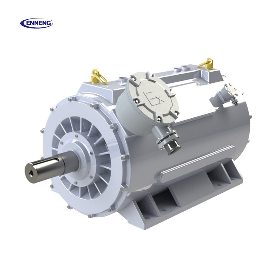
A Direct Drive Motor is especially worth evaluating when the load operates slowly for long periods, needs high torque at low speed, or must reverse accurately. There is a practical limit: if the application needs a large speed reduction and a compact motor cannot provide the required torque, a gearbox may remain the sound engineering choice. Removing a reducer without revalidating the motor and load design merely transfers the risk elsewhere.
How direct drive shifts reliability work into better design decisions
Once the gearbox is gone, reliability depends more visibly on the motor, controller, mounting, and driven machine. This is usually a manageable trade because those items can be specified together rather than treated as separate components. The design review should cover the following points.
1. Verify continuous and peak torque margins
Use the full duty cycle, not just rated load. Starts, jams, indexing, process transients, and reversals may create short torque demands that determine motor and drive sizing. A high-torque low-speed configuration should have a defined thermal basis for its continuous operating point.
2. Check thermal conditions at the installation
Direct drive can put substantial torque density near the process. Ambient temperature, enclosure ventilation, cooling method, contamination, and duty cycle therefore matter. A nameplate efficiency class is useful context—IEC 60034-30-1 provides a framework for motor efficiency classes—but it is not a substitute for application-specific thermal validation.
3. Design the load-side support, not just the motor connection
Directly coupling a motor to a poorly supported roll, drum, screw, or mixer does not remove bending loads or process shock. Confirm shaft support, allowable loads, mounting stiffness, concentricity, and how the driven machine handles external forces. Treat the motor-to-load connection as its own mechanical review instead of relying on a generic gearbox-interface check.
4. Use controls to prevent overload events
Appropriate current limits, acceleration ramps, torque limits, feedback, and fault handling can keep abnormal events from becoming mechanical damage. The control strategy should reflect the process: a conveyor jam, a high-inertia fan restart, and a reversing indexer do not call for the same response.
Where a Gearless Motor architecture is most persuasive
A Gearless Motor configuration tends to be compelling where gearbox access is difficult, downtime has a high operational cost, or the application values smooth low-speed torque and precise motion. Examples may include conveying, winding, rotary tables, mixers, pumps, fans, and specialized process equipment. The right case depends on load behavior and installation constraints, not on a blanket claim that gearless systems suit every machine.
For remote or maintenance-sensitive sites, the maintenance argument can be particularly strong. Eliminating a reducer removes the routine need to manage that reducer’s lubrication condition, seals, and internal wear. It does not remove the need for electrical inspection, mounting checks, controller diagnostics, or driven-equipment maintenance; it makes the maintenance plan narrower and more transparent.
A practical evaluation checklist before replacing a transmission
- Map every present mechanical component from motor shaft to load and identify its failure and maintenance modes.
- Measure or calculate the real torque-speed cycle, including starts, reversals, overloads, and inertia.
- Confirm whether a Direct Drive Motor can meet continuous and peak torque requirements at the required speed.
- Review thermal conditions, ingress protection needs, cooling, and the applicable efficiency requirements for the installation.
- Check load-side bearings, shaft stiffness, mounting accuracy, and allowable radial and axial forces.
Direct drive commissioning record: questions that expose avoidable risk
Use this commissioning review to evaluate the Direct Drive Motor and the Gearless Motor architecture as a complete machine rather than as a component swap.
- For the Direct Drive Motor, record continuous and peak torque, mounting flatness, feedback integrity, enclosure suitability, and safe-stop behavior.
- For the Gearless Motor, document duty-cycle temperature, cooling conditions, driven-shaft runout, load-side bearing support, and the jam-clearing response.
- For the Direct Drive Motor, retain torque, thermal, and current baselines; for the Gearless Motor, assign clear ownership for inspection and controller diagnostics.
A Direct Drive Motor installation is easier to diagnose when those records exist. A Gearless Motor does not erase process variation, but it shortens the mechanical path and helps isolate deviations.
The ENNENG Customisation Advantage
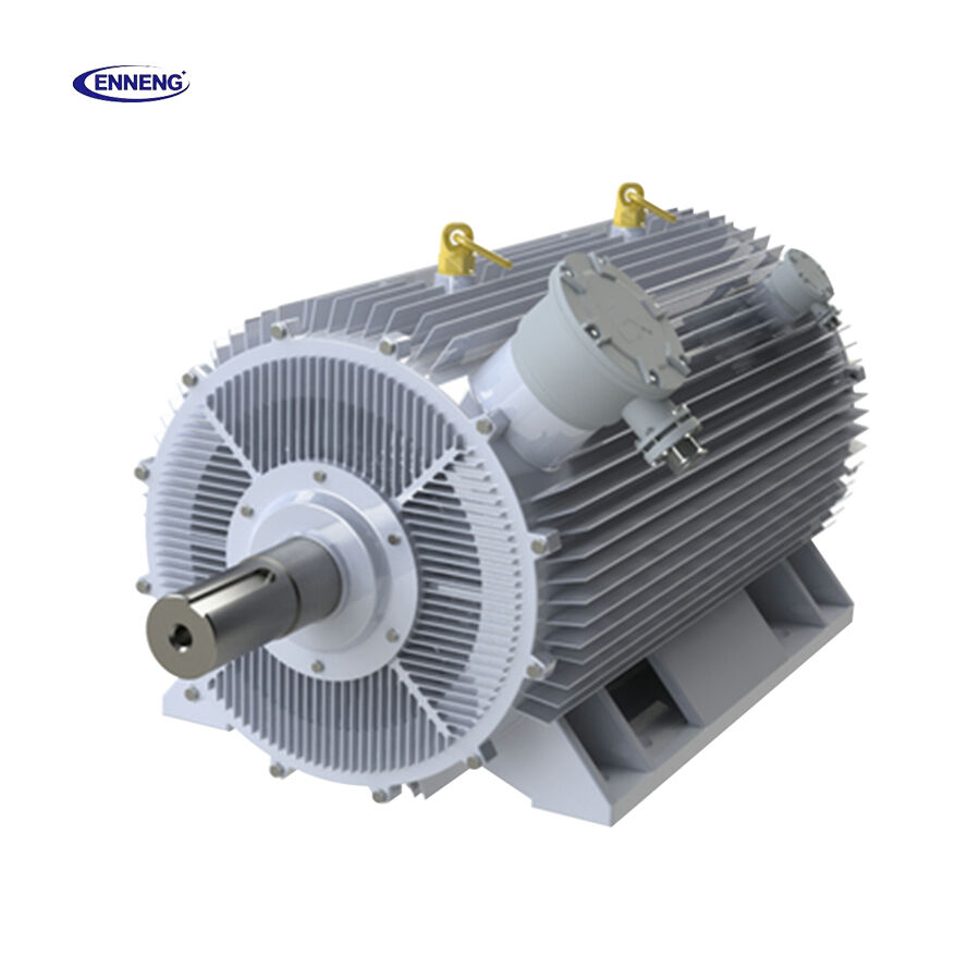
No two industrial facilities share the same spatial or mechanical constraints. ENNENG stands out because we do not just supply off-the-shelf catalogue products; we specialise in delivering a tailor-made permanent magnet motor tailored to your specific application .
Supported by our elite R&D team consisting of engineers from the National Rare Earth Permanent Magnet Engineering Centre, and backed by dozens of patents, we customise high-voltage (6kV/10kV) and low-voltage (380V/660V/1140V) solutions to match your existing footprint. From water treatment facilities and oil wells to explosion-proof mining environments, we deliver optimal performance where general-purpose motors fail .
If you are evaluating commercial permanent magnet motors for sale and need an engineered drive solution that guarantees efficiency and longevity, ENNENG is your trusted partner.Contact ENNENG Today.Speak to our technical engineering team to receive a customised drive proposal.
- WhatsApp: +86 18562780228
- E-Mail: [email protected]
- Phone: +86 532 66000559
Conclusion: simplify the failure path, then validate the application
A Direct Drive Motor lowers failure risk by removing intermediate mechanical elements that often need lubrication, alignment, sealing, and wear management. The reliability gain is most credible when it is treated as a system-design decision: correctly size torque and thermal capacity, support the driven load properly, and tune the controls for the real duty cycle.
For industrial teams, that is the practical value of direct drive. It replaces a chain of interacting transmission risks with a shorter, more inspectable path from electrical torque to useful work—while preserving the engineering discipline needed to make the simplified system reliable.

