
 EN

Aging workshops rarely have one obvious motor problem. They have a mix of production bottlenecks, maintenance habits, overloaded feeders, legacy starters, and equipment that has been modified more than once. An Energy Saving Motor Solution should therefore begin before a purchase order or a motor nameplate comparison. It starts with a pre-transformation assessment that defines what the existing system actually does, where its losses and risks sit, and whether a permanent-magnet retrofit is technically justified.
For plant engineers and maintenance managers, this is the difference between replacing a motor and redesigning a workable motor system. The assessment below is especially useful when considering Retrofit Induction to PMSM projects in workshops with long operating histories, variable production loads, or limited shutdown windows.
Why an aging workshop needs a system-level assessment
An electric motor does not operate alone. It works with driven equipment, transmissions, process controls, protection devices, cabling, and operator practices. That is why an Energy Saving Motor Solution should examine the motor system rather than treating rated power as the entire specification.
It is true that a high-efficiency motor can reduce losses, but efficiency at rated load is only one part of the decision. The shift that matters is from chasing peak efficiency to matching the duty cycle. A motor that spends much of its time at partial load, starts frequently, runs through a VFD, or faces unstable voltage needs a different assessment from a continuously loaded motor on a direct-on-line starter.
Before looking at a proposed replacement, ask: what is the actual process demand over a typical shift, and when does it differ from the nameplate condition? This question makes the assessment more useful than a simple “old versus new” motor comparison.
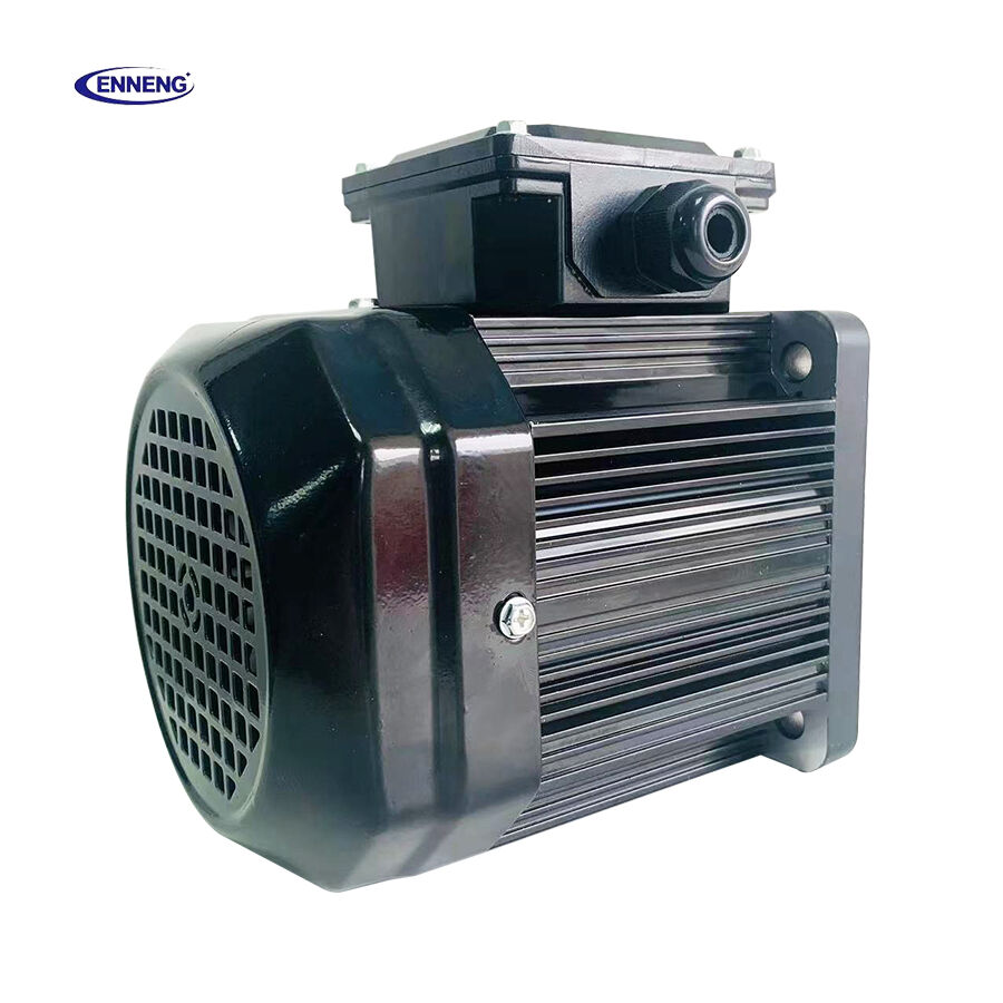
Step 1: Build a reliable motor and process inventory
The first field task is to identify every candidate motor and connect it to the process it drives. Create one record per motor rather than grouping units only by rated power. The record should include:
- motor location, driven equipment, and production function;
- rated kW, voltage, frequency, poles, speed, enclosure, mounting, and efficiency class where readable;
- installation year, repair history, bearing or insulation observations, and unplanned-stop history;
- starter or VFD type, protection settings, cable condition, and available panel space;
- operating hours, start-stop frequency, process setpoint, and whether the load is constant, variable-torque, or cyclical.
Photographs of nameplates, terminal boxes, couplings, foundations, and control cabinets help resolve inconsistencies later. In older buildings, the motor label may no longer match a rewound unit or a changed process load. An Energy Saving Motor Solution that ignores this possibility can be sized around an outdated assumption.
Step 2: Measure the duty cycle instead of assuming rated load
Collect measurements during representative production, not only during a quiet inspection. Log current, voltage, power factor, running speed where practical, operating temperature, starts, and load changes across at least the meaningful operating states. For pumps and fans, note valve or damper position. For conveyors, mixers, crushers, and machine tools, note material flow, peak events, idle time, and any mechanical shock.
Variable-frequency drives can help motor systems follow variable process demand, but only where the driven load, control logic, and motor-drive pairing support it. The assessment must therefore separate a variable-load opportunity from a problem caused by poor process control. A VFD is not automatically the answer; it must be matched to the actual torque curve and operating envelope.
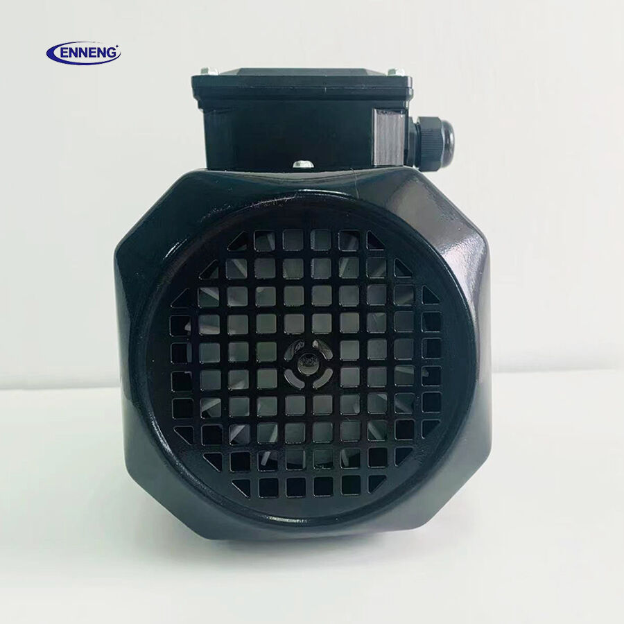
When planning a Retrofit Induction to PMSM conversion, capture partial-load behavior carefully. Permanent-magnet motors may offer a useful efficiency profile in suitable applications, yet the expected result still depends on speed range, loading, ambient conditions, and the selected control method.
Step 3: Check mechanical integration before selecting a replacement
Mechanical data can rule out an otherwise attractive retrofit. Verify shaft height, frame size, foot or flange mounting, shaft diameter and extension, coupling condition, pulley or gearbox alignment, vibration history, ventilation clearance, and permissible service access. Evaluate the driven machine as part of the decision: a worn pump, misaligned belt drive, restricted fan duct, or overloaded gearbox can keep wasting energy after the motor is changed.
Evaluating a motor in isolation without accounting for its coupling, driven equipment, and control system often produces a technically correct specification that still underperforms in the field. An Energy Saving Motor Solution should turn these observations into an installation plan, including any adapter work, alignment checks, and acceptance measurements required after commissioning.
Step 4: Review electrical and control compatibility
Next, review the supply and control architecture. Record feeder capacity, voltage balance, grounding, harmonic conditions where VFDs are present, protection coordination, cable length, bypass requirements, emergency-stop logic, and communications interfaces. Determine whether the proposed motor will run direct on line, with a soft starter, or with a compatible drive.
Efficiency classifications should also be read in context. IEC 60034-30-1 provides the IE1, IE2, IE3, and IE4 efficiency-class framework for applicable motors. That framework is useful for comparing specifications, but it does not replace a site assessment. The right class, rating, and control arrangement depend on the duty cycle and local requirements, not on a label alone.
Temperature deserves the same caution. If the workshop is hot, dusty, poorly ventilated, or at unusual altitude, nameplate assumptions may not reflect the required continuous operating margin. Confirm ambient conditions, enclosure needs, and thermal clearance before finalizing the Energy Saving Motor Solution.
Step 5: Define the retrofit case and its decision criteria
Once field data is available, compare the current arrangement with the proposed configuration. The case should state the process objective, baseline operating pattern, expected technical changes, installation scope, production constraints, and verification method. Do not promise a fixed savings figure before the baseline and duty cycle are established.
For each Retrofit Induction to PMSM candidate, use a practical decision table:
|
Assessment area |
Question to resolve |
Decision impact |
|
Duty cycle |
Does the motor operate at varying load or speed for meaningful hours? |
Determines whether a motor-and-drive change may fit the process. |
|
Mechanical fit |
Can the replacement be mounted, aligned, cooled, and serviced safely? |
Defines adapter work, shutdown scope, and installation risk. |
|
Electrical fit |
Are supply, protection, controls, and drive settings compatible? |
Prevents nuisance trips and commissioning rework. |
|
Process risk |
What happens if speed, torque, or restart behavior changes? |
Sets trial, bypass, and acceptance-test requirements. |
|
Verification |
Which pre- and post-retrofit measurements will be compared? |
Creates an auditable basis for evaluating results. |
Step 6: Plan commissioning and verification before shutdown
Most buyers expect a retrofit to be operational quickly after delivery; experienced teams plan parameter setting, rotation checks, alignment, no-load trials, loaded trials, protection validation, and operator handover as a separate commissioning phase. Prepare rollback conditions and a clear acceptance plan before the outage begins.
Post-retrofit verification should compare like-for-like production periods where possible. Track electrical input, process output, temperature, vibration, alarms, and operator observations. This does not turn every project into a laboratory test; it simply gives the maintenance team evidence to decide whether the Energy Saving Motor Solution is performing as intended and where further optimization is needed.
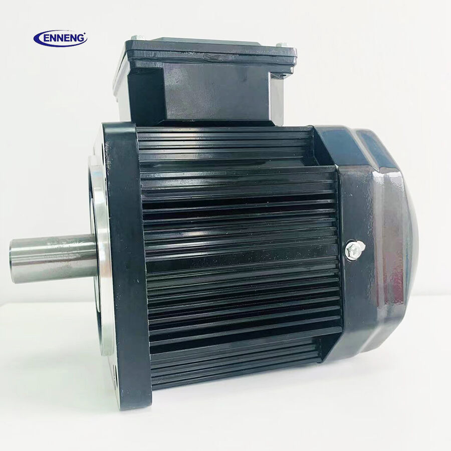
The ENNENG Customisation Advantage
No two industrial facilities share the same spatial or mechanical constraints. ENNENG stands out because we do not just supply off-the-shelf catalogue products; we specialise in delivering a tailor-made permanent magnet motor tailored to your specific application .
Supported by our elite R&D team consisting of engineers from the National Rare Earth Permanent Magnet Engineering Centre, and backed by dozens of patents, we customise high-voltage (6kV/10kV) and low-voltage (380V/660V/1140V) solutions to match your existing footprint. From water treatment facilities and oil wells to explosion-proof mining environments, we deliver optimal performance where general-purpose motors fail .
If you are evaluating commercial permanent magnet motors for sale and need an engineered drive solution that guarantees efficiency and longevity, ENNENG is your trusted partner.Contact ENNENG Today.Speak to our technical engineering team to receive a customised drive proposal.
- WhatsApp: +86 18562780228
- E-Mail: [email protected]
- Phone: +86 532 66000559
A practical starting point for workshop transformation
A strong pre-transformation assessment converts scattered workshop knowledge into a defensible retrofit scope. It identifies which machines are viable candidates, which constraints need engineering work first, and which measurements will prove the outcome. For an aging manufacturing workshop, that preparation can prevent a quick nameplate substitution from becoming a costly rework exercise.
ENNENG focuses on permanent-magnet motor design and manufacturing and can support technical discussions around application-specific motor selection. Start with the site data, the duty cycle, and the integration constraints; then develop an Energy Saving Motor Solution that is appropriate for the process rather than merely newer than the motor it replaces.

