
 EN

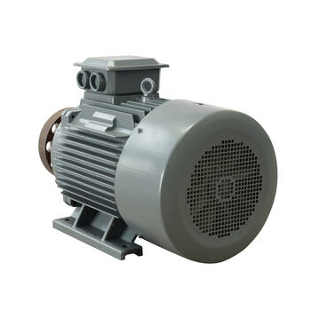
A Permanent Magnet Generator PMG does not create fixed voltage and frequency by itself when its shaft speed changes. In a wind, micro-hydro, engine-driven, or other variable-speed system, rotational speed changes the generator’s raw electrical output. Stable power at the battery, inverter, load bus, or grid connection comes from treating the Permanent Magnet Generator PMG as one part of a controlled power-conversion system.
That distinction matters in remote and off-grid projects. A generator nameplate can describe a rated operating point, but the site operates across many points. The practical question is not “Does the generator make power?” but “Can the complete system capture changing mechanical power, keep electrical limits safe, and deliver usable energy to the load?”
Why raw PMG output moves with rotational speed
A Permanent Magnet Generator PMG uses rotor magnets instead of a separately excited rotor field winding. As the rotor turns, its magnetic field cuts the stator windings and induces AC voltage. More speed generally means the magnetic field passes the stator windings more often per second, so output frequency rises. The induced voltage also tends to rise with speed until design limits and loading effects become significant.
This is why a variable-speed turbine cannot normally send the generator terminals directly to a fixed-voltage AC load. At low speed, voltage may be insufficient; at high speed, voltage can exceed what downstream equipment is designed to accept. A changing electrical load adds another layer: current draw creates voltage drop in the windings and cable, while excessive current produces heat.
The important correction is that variable raw output does not mean unstable usable power. It means the Permanent Magnet Generator PMG needs an electrical interface that decouples shaft-speed variation from the voltage and frequency required by the application.
The control chain that turns variable generation into stable power
In most modern variable-speed systems, the control chain has five jobs: convert the generator’s variable-frequency AC, establish a controlled energy buffer, regulate the output, match available mechanical power, and protect the equipment. The exact topology differs for battery charging, standalone AC, and grid-connected applications, but the logic is consistent.
1. Rectify the generator output
A three-phase Permanent Magnet Generator PMG commonly feeds a diode bridge or an actively controlled rectifier. Rectification changes variable-frequency AC into DC. A passive bridge is simple, while an active rectifier gives the controller more authority over generator current and torque. Neither choice removes the need to size cables, thermal paths, and protection for the actual operating envelope.
2. Stabilize the DC link
After rectification, capacitors—and in some systems batteries or a DC/DC stage—form a DC link. This stage absorbs short-term ripple and lets a controller maintain a target DC voltage range. Research on PMG–rectifier control has demonstrated regulated DC-link behavior across different generator line frequencies; it is an illustration of control architecture, not a universal voltage setpoint for every project.
A Permanent Magnet Generator PMG therefore does not need to spin at one fixed RPM for the end user to see a stable DC bus. The converter observes bus voltage, current, speed or electrical frequency, and temperature, then changes its switching or loading behavior within permitted limits.
3. Invert or convert for the end use
For battery systems, a charge controller or DC/DC converter conditions charging current and prevents over-voltage. For a fixed AC load, an inverter synthesizes the required voltage and frequency from the DC link. For grid-connected systems, power electronics synchronize the delivered waveform with the grid and enforce connection rules. The stable 50 Hz or 60 Hz output belongs to the inverter-controlled interface, not to the raw terminals of a variable-speed Permanent Magnet Generator PMG.
How load control protects both output stability and the generator
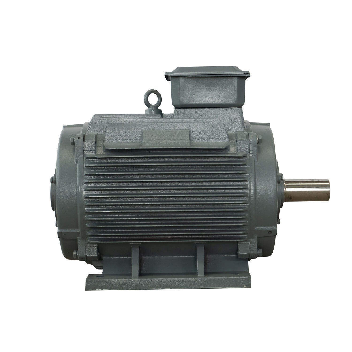
Electrical loading is also mechanical loading. When the controller draws more current, electromagnetic torque opposing the shaft rises. When it draws less, the prime mover can accelerate. This gives a Permanent Magnet Generator PMG system a useful control handle: command generator current so the turbine, engine, or hydraulic runner stays near an appropriate operating point while the DC bus stays within its allowable range.
Maximum-power-point tracking is one example. In variable wind, an MPPT controller estimates or measures a suitable operating point and adjusts electrical loading to capture energy without forcing the rotor to an inefficient speed. It is not magic: if the wind resource or mechanical input is low, the controller cannot manufacture rated power. It can make the available energy more usable and prevent the system from chasing an unsuitable fixed-speed target.
At the other end of the range, a Permanent Magnet Generator PMG installation needs overspeed and over-voltage strategies. Depending on the prime mover and project design, these can include blade pitch or furling control, a mechanical brake, a diversion or dump load, converter current limits, and controlled shutdown. The design must coordinate them; relying on one component to absorb every abnormal condition is poor practice.
Where Permanent Magnet Motor PMSM principles fit
A Permanent Magnet Motor PMSM and a PMG share the same permanent-magnet electromagnetic foundation, but their energy direction differs. A PMSM normally receives controlled electrical power to create shaft torque; a generator receives shaft torque to create electrical power. The same idea of vector control is relevant: controlling stator current affects electromagnetic torque. In a generator system, that relationship lets the converter regulate loading on the rotor.
This connection is useful when specifying a drive-generator package. Control teams should confirm sensing, firmware modes, fault behavior, and thermal assumptions rather than assuming a controller configured for a Permanent Magnet Motor PMSM will automatically handle generator operation. The hardware may be related, but the operating objectives and protection logic are not identical.
What to verify before calling output “stable”
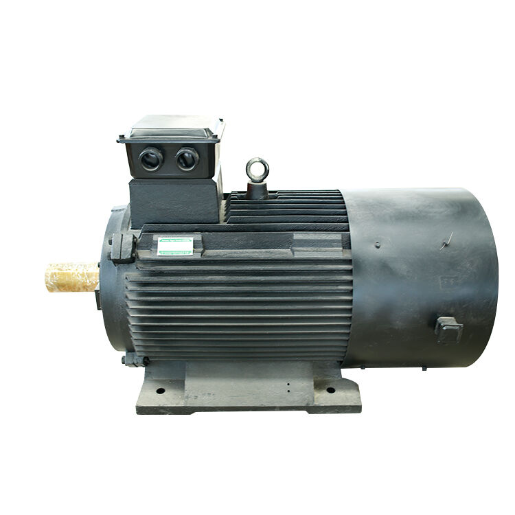
A stable Permanent Magnet Generator PMG system should be checked as a system, not only by its generator datasheet. Start with the speed range and torque curve of the prime mover. Then document the expected generator voltage and frequency range, rectifier or converter ratings, DC-link limits, cable voltage drop, battery acceptance limits or inverter requirements, grounding, and fault protection.
- Measure the real speed envelope: confirm normal, gust, start-up, and fault conditions rather than using a single nominal RPM.
- Check the conversion stages together: verify that the rectifier, DC link, controller, and inverter share compatible voltage and current limits.
- Test load steps: observe DC-bus recovery, output waveform, current limiting, and temperature when loads change abruptly.
- Plan for excess energy: specify what happens when mechanical input exceeds load or battery acceptance.
- Commission the installation: examine wiring resistance, connector quality, grounding, and control settings; system losses can be mistaken for a generator problem.
Choosing the right stability strategy
There is no universal control package for every Permanent Magnet Generator PMG. A compact battery-charging system may use rectification, a purpose-built charge controller, and a diversion load. A remote AC microgrid may need a robust DC link, inverter controls, and storage coordination. A grid-connected wind system requires a converter designed for synchronization, grid-code behavior, and protection.
For remote, island, mountain, and distributed-energy projects, the most reliable specification conversation begins with site data: speed range, mechanical input profile, ambient conditions, cable distance, storage, loads, and service access. A supplier with application-specific design and winding capability can help align generator voltage, phases, thermal design, and controller compatibility to those conditions. That process makes a Permanent Magnet Generator PMG part of a stable power system rather than an isolated component expected to solve every variation on its own.
If you are evaluating commercial permanent magnet motors for sale and need an engineered drive solution that guarantees efficiency and longevity, ENNENG is your trusted partner.Contact ENNENG Today.Speak to our technical engineering team to receive a customised drive proposal.
- WhatsApp: +86 18562780228
- E-Mail: [email protected]
- Phone: +86 532 66000559

