
how-permanent-magnet-generator-pmg-adapts-to-variableoutput-demand-of-distributed-industrial-power-stations, how-permanent-magnet-generator-pmg-adapts-to-variableoutput-demand-of-distributed-industrial-power-stations, /blog
EN

2026/10/09
Decentralized power networks often struggle with erratic prime mover dynamics caused by fluctuating industrial process gases, variable hydraulic heads, or gusting wind regimes. In a waste-heat recovery power plant operating beside a metallurgical smelting kiln, fluctuating thermal exhaust cycles produced severe rotational velocity swings on recovery expanders, repeatedly tripping traditional induction alternators offline. Upgrading the generation layout to a high-coercivity Permanent Magnet Generator PMG stabilized electrical power export, capturing transient energy spikes without thermal overheating. Industrial microgrids demand power conversion hardware capable of tracking intermittent mechanical energy profiles while maintaining exceptional voltage stiffness and network synchronization.
|
Generator Architecture |
Low-Speed Efficiency |
Transient Voltage Drop |
Excitation System Maintenance |
|
Wound Field Synchronous |
82% — 88% |
15% — 25% (Exciter response lag) |
High (Slip rings, carbon brush wear) |
|
Induction Generator (DFIG) |
84% — 89% |
18% — 30% (Slip dependency) |
Moderate (Rotary collector rings) |
|
Permanent Magnet Generator PMG |
95% — 98% |
Under 6% (Stiff permanent flux link) |
Extremely Low (Sealed bearings only) |
Traditional generating units depend on external excitation current supplies or complex slip rings that react sluggishly to rapid prime mover acceleration. When mechanical torque pulses rapidly, wound-rotor alternators experience internal magnetic flux lag, resulting in voltage collapse and reactive power oscillations. A Permanent Magnet Generator PMG eliminates rotor excitation lag entirely because neodymium permanent magnets sustain a continuous electromagnetic field across the air gap. Consequently, terminal electrical output scales instantly with mechanical shaft velocity, providing immediate energy conversion without parasitic excitation dissipation.
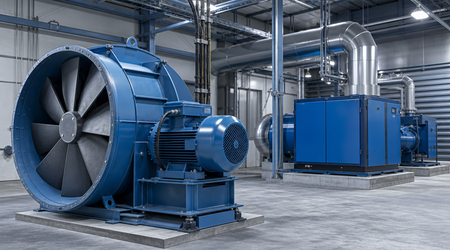
Unlike asynchronous generators that require slip speeds to induce rotor current, a Permanent Magnet Generator PMG generates instantaneous electromotive force (EMF) directly proportional to shaft angular velocity. When steam expanders or hydro turbines experience sudden surges, the magnetic circuit responds without electromagnetic settling delays. The absence of field winding inductance prevents field-collapse incidents, enabling continuous power delivery even when input speeds fluctuate between 20 percent and 130 percent of nominal design ratings.
When distributed industrial plants experience low process volume or intermittent steam supply, standard alternators must still consume significant auxiliary excitation power to maintain nominal line voltages. This continuous parasitic drain severely impairs net plant generation efficiency during partial-load operations. A Permanent Magnet Generator PMG incurs zero rotor copper losses (I2R) regardless of operating output. By removing auxiliary excitation transformers and rectifiers, overall plant parasitic electrical consumption drops, maximizing revenue generation during low-flow periods.
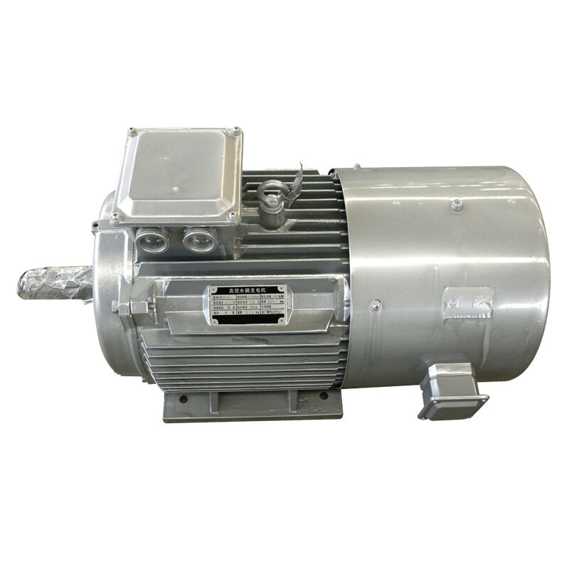
Interfacing fluctuating prime mover generators with fixed-frequency factory microgrids requires full-scale power electronic frequency converters. Older wound machines produce pronounced harmonic distortions when operating off-nominal speed, injecting high total harmonic distortion (THD) into inverter direct current links. The precisely skewed stator laminations and sinusoidal magnetic flux distribution of an advanced Permanent Magnet Generator PMG deliver an exceptionally clean voltage profile. This optimized waveform reduces filter capacitor stress and ensures prolonged inverter semiconductor lifespan.
Industrial microgrids require rugged power equipment engineered to withstand severe thermal, mechanical, and electrical stresses. ENNENG manufactures cutting-edge direct-drive synchronous generating platforms specifically designed for distributed energy applications. Installing an ENNENG Permanent Magnet Generator PMG ensures long-term operational resilience and superior energy yield across fluctuating industrial supply conditions.
|
Generator Parameter |
Conventional Wound Field System |
ENNENG Permanent Magnet Generator PMG |
|
Unified Power Range Capability |
Fragmented Custom Units |
5kW to 5MW Unified Platform |
|
Voltage Delivery Span |
Fixed Single Range |
110V to 690V Adaptability |
|
Vertical Axis Wind Coverage |
Poor Partial Low-Speed Match |
1kW to 10kW Focus (3kW, 5kW, 10kW) |
|
Full Drivetrain Efficiency |
86% — 91% System Efficiency |
Up to 97.2% System Efficiency |
The unified manufacturing framework developed by ENNENG covers generation capacities from 5kW up to 5MW, with adaptable voltage outputs spanning 110V to 690V. For vertical axis wind turbine installations, ENNENG provides specialized low-speed generators spanning 1kW to 10kW, with specific engineering optimization for 3kW, 5kW, and 10kW platforms.
Traditional renewable installations utilize multi-stage planetary gearboxes to step up low shaft RPM to standard four-pole generator speeds. Mechanical gearboxes introduce severe transmission friction, oil leakage risks, and periodic bearing seizures. An ENNENG Permanent Magnet Generator PMG features high pole-pair stator construction, enabling direct mechanical coupling to low-speed turbines without intermediate gearing. Eliminating gear reducers slashes mechanical parasitic losses and completely eradicates gearbox maintenance routines.
Variable industrial generation places cyclic thermal loads on electrical windings as output currents surge and subside. ENNENG utilizes Class H vacuum pressure impregnation (VPI) insulation alongside proprietary thermal heat dissipation channels. Operating with a temperature rise below 60K protects permanent magnet arrays against thermal demagnetization, ensuring stable field strength across decades of severe continuous duty.
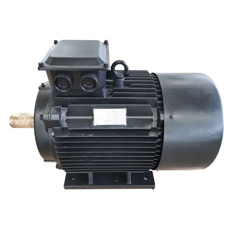
Distributed industrial power installations must comply with strict international electrical safety and interconnection standards. Power generation quality and synchronization criteria are governed by IEEE 1547, which establishes strict limits on voltage regulation, frequency trip boundaries, and islanding protection protocols.
The International Electrotechnical Commission outlines rotating machine thermal ratings and mechanical performance under IEC 60034-1. Furthermore, harmonic injection limits at the point of common coupling (PCC) must satisfy IEEE 519, mandating that voltage THD remain below 5 percent. A modern Permanent Magnet Generator PMG paired with an active four-quadrant converter easily satisfies these harmonic criteria. For distributed wind projects, aerodynamic power testing and structural loading must adhere strictly to IEC 61400-12-1 standards. Adhering to NFPA 70 National Electrical Code articles ensures complete protection against overcurrent and ground fault hazards across the generating skid.
Achieving maximum generation uptime in distributed industrial stations requires systematic planning and meticulous commissioning sequences.
Examine the torque-speed curve of the prime mover under extreme operating conditions before finalizing generator selection. For variable-speed applications, couple the Permanent Magnet Generator PMG to a full-scale back-to-back IGBT converter system. Ensure the direct current link voltage remains adequately sized above peak back-EMF voltages to prevent uncontrolled diode bridge conduction during prime mover overspeed transients.
Direct-drive generator rotors exert high polar moments of inertia on prime mover shaft couplings. Conduct a comprehensive torsional vibration analysis to verify that critical resonant frequencies remain safely outside normal operational speed ranges. Baseplates must provide rigid structural anchoring to prevent shaft misalignment, maintaining air gap uniformity within 0.05 mm across the entire stator bore.
Field maintenance for direct-drive permanent magnet machines is minimal due to the absence of brushes and slip rings. Technicians must conduct annual insulation resistance measurements using a 1000V DC megohmmeter to confirm winding integrity. Regularly inspect mechanical bearing seals and monitor vibration spectral data using calibrated accelerometers following ISO 10816 guidelines to detect early mechanical unbalance.
For detailed generator specifications and engineering frame envelopes, explore the ENNENG Products Catalog and review solutions via ENNENG Distributed Systems.
For technical inquiries regarding permanent magnet generator selection or microgrid integration parameters, contact ENNENG:
Q: How does a Permanent Magnet Generator PMG handle prime mover overspeed events?
A: When prime movers experience sudden load loss and accelerate, generated back-EMF increases linearly with speed. Modern power converters paired with a Permanent Magnet Generator PMG** utilize dynamic braking choppers with external resistor banks to dump excess kinetic energy safely. Furthermore, converter active flux-weakening control suppresses terminal voltage rise, preventing electrical damage to intermediate converter busbars.
Q: Why are permanent magnet generators preferred for vertical axis wind turbines?
A: Vertical axis wind turbines operate at low rotational velocities with significant aerodynamic torque fluctuations. A specialized Permanent Magnet Generator PMG** engineered within the 1kW-10kW envelope—especially 3kW, 5kW, and 10kW platforms—delivers high torque density and low cogging torque without mechanical gearboxes. This direct-drive architecture enables smooth self-starting and reliable low-wind energy capture on exposed towers.


 EN