
 EN

How Permanent Magnet Generator PMG Copes with Large-Amplitude Rotation-Speed Fluctuation in Industrial Waste-Heat-Recovery Systems
Industrial waste-heat-recovery equipment rarely sees the steady shaft speed implied by a nameplate. Heat-source temperature, flow, working-fluid pressure, condenser conditions, and process throughput can all move together. An expander or turbine may therefore accelerate sharply after a disturbance and then settle at a much lower speed. A Permanent Magnet Generator PMG can work well in that environment, but the machine alone is not the solution. Its electromagnetic design, shaft-line dynamics, cooling, power converter, and protection logic have to be specified as one operating envelope.
As an engineer reviewing variable-speed energy systems, I start with the measured speed and torque envelope rather than a peak kW figure. That distinction matters: a technically sound generator can still be paired with a converter that trips too early, a coupling that amplifies torsional motion, or a controller that lets a thermal transient become a mechanical overspeed event.
Why waste-heat recovery produces large speed swings
In an organic Rankine cycle, a steam cycle, or another expander-based recovery loop, shaft power follows the available enthalpy drop and mass flow. Those inputs are not fixed when the host furnace, compressor, engine, kiln, or process line changes duty. Condensing conditions also shift with ambient temperature and cooling-water performance. The result can be a wide speed range during start-up, load rejection, heat-source changes, bypass events, and normal part-load operation.
Speed affects a PMG directly. For a given magnetic design, generated voltage and electrical frequency rise with rotational speed. Torque demand, iron loss, windage, bearing loss, rotor stress, and inverter switching conditions must all be evaluated across the permitted range. Treating the rating as a single fixed number is useful for rough planning; once the system experiences a rapid speed excursion, usable output and thermal margin can shift considerably.
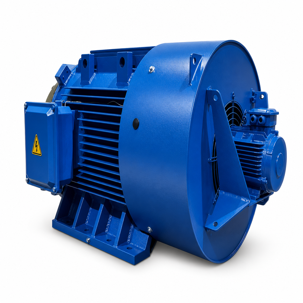
A published high-speed waste-heat power module illustrates the system principle rather than a universal specification: it described operation from 15,000 to 26,500 rpm and a converter that changed variable-frequency generator output into 400–480 Vac, 50/60 Hz power. The important lesson is that variable speed is expected and managed at system level; it is not assumed away.
What a Permanent Magnet Generator PMG contributes
A Permanent Magnet Generator PMG has a rotor magnetic field without rotor excitation current or slip rings. That removes one source of rotor losses and excitation-system complexity. In compact, high-speed waste-heat packages, the resulting power density and efficient operation can be attractive. However, permanent magnets also mean the air-gap flux is present whenever the rotor turns. During overspeed or an open-circuit event, the control system cannot simply turn off field current as it might in a wound field machine.
That is why the PMG specification must state more than nominal voltage and power. It should define continuous and transient speed limits, the voltage-versus-speed curve, allowable terminal conditions, rotor retention design, demagnetization margin, insulation thermal class, cooling assumptions, and allowable vibration. IEC 60034-1 is commonly considered for rotating-machine ratings and performance, while IEC 60034-14 addresses factory vibration testing for applicable machines; the project team should confirm the editions and scope that apply to its contract.
The converter decouples generator speed from grid frequency
The most useful architecture for severe speed variation is normally a full power-electronic interface: generator-side controlled rectification, a DC link, and a grid-side inverter or a controlled DC output stage. This arrangement lets the Permanent Magnet Generator PMG produce variable voltage and frequency while the downstream electrical system receives regulated power.
- Generator-side control regulates electromagnetic torque. It can load the shaft during acceleration, limit current, and follow an optimum or safe speed trajectory.
- DC-link management absorbs the mismatch between mechanical input and electrical export for short intervals. Its voltage limits must coordinate with braking, curtailment, and grid-fault behavior.
- Grid-side control manages exported active and reactive power, synchronization, harmonics, and fault ride-through where required.
- Protection logic supervises overspeed, overvoltage, overcurrent, loss of load, converter availability, and thermal sensors; it must act before rotor or insulation limits are approached.
It is true that a full converter adds cost and control complexity. But where the thermal source varies widely, direct connection of a variable-speed PMG to a fixed-frequency bus transfers the difficulty elsewhere. The better question is whether the converter, dump-load path, and shutdown sequence can safely handle the energy stored in the rotating assembly when the electrical load suddenly disappears.
Mechanical design matters as much as electrical control
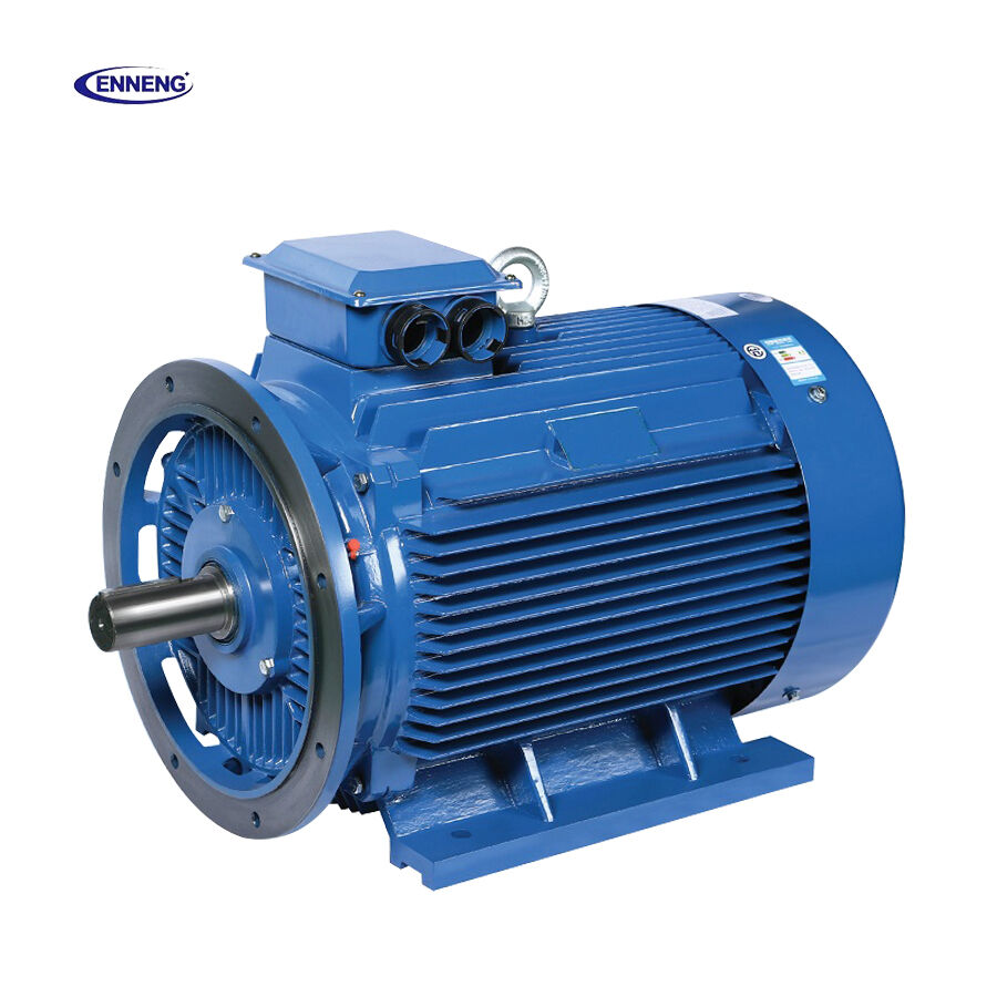
Large amplitude speed fluctuation is also a mechanical problem. The turbine or expander, coupling, PMG rotor, bearings, baseplate, and enclosure form a dynamic system with critical speeds and torsional modes. A rapid torque change can excite resonance even when average power is modest. In field troubleshooting, vibration is often traced to mounting stiffness, alignment, coupling behavior, or baseplate resonance rather than to a generator winding fault.
For that reason, the design review should include a torsional analysis, rotor-dynamic assessment, run-up and coast-down paths through critical speeds, balancing requirements, bearing limits, and vibration acceptance criteria. High-speed systems may use specialized bearing and containment arrangements, but the selected approach should follow the actual speed range, environment, maintenance plan, and consequence of failure. Evaluating the generator in isolation from the expander, converter, and support structure often creates a correct datasheet that underperforms in service.
Thermal margins and magnet protection under transients
Speed changes affect losses differently. Copper loss follows current, while core loss and windage generally increase with speed; airflow and coolant conditions may also change during a process transient. The thermal model therefore needs both steady operating points and transient duty cycles. Temperature sensors in stator windings, bearings, coolant paths, and—where practical—the rotor environment provide the controller with better protection than a single enclosure temperature.
Magnet material and rotor retention must be selected against the worst combination of temperature, centrifugal stress, and fault current. A Permanent Magnet Generator PMG should not be credited with unlimited overload capacity simply because its normal efficiency is high. Design margins, sensor plausibility checks, and conservative trip thresholds are what preserve the magnets and insulation when a heat-source upset develops faster than the thermal loop can respond.
Permanent Magnet Motor PMSM technology: related, but not interchangeable
Permanent Magnet Motor PMSM technology shares the same broad machine family: permanent magnets create rotor flux and an inverter controls stator currents. The control vocabulary—current vectors, torque limits, rotor position or speed feedback, and thermal derating—can be relevant when a PMG drive and a PMSM share a DC bus. Still, a generator in a waste-heat expander must be designed around generating voltage, fault energy, overspeed, and turbine dynamics. A PMSM control approach should be adapted, not copied without a generator-specific protection review.
A practical specification and commissioning sequence
- Measure or model minimum, normal, maximum, acceleration, and emergency coast-down speeds for the real thermal process.
- Define torque-speed and power-speed envelopes, including low-load operation, loss of grid, heat-source step changes, and cooling degradation.
- Match the PMG voltage-frequency characteristic to the converter input range, current limit, DC-link voltage, and braking or dump-load capacity.
- Review rotor dynamics, coupling torsion, mounting stiffness, alignment, balancing, and vibration criteria before finalizing the package layout.
- Validate thermal behavior with transient tests, not only a rated-point heat run; record winding, bearing, coolant, and converter temperatures.
- Commission protection sequences for overspeed, converter trip, sensor failure, loss of load, and controlled shutdown, then document the accepted limits.
Engineering Consultation and Drive Upgrade Inquiries
Determining the precise operational savings of a Permanent Magnet Synchronous Motor upgrade begins with a detailed assessment of facility load profiles, feeder impedance, and utility billing structures. Transitioning production assets to permanent magnet motor systems mitigates harmonic stress, lowers apparent current demand, and elevates overall facility energy efficiency. Application specialists provide comprehensive electrical system modeling, shaft interface engineering, and turnkey drive selection support. Contact the engineering team today to review specific plant parameters and project requirements.
- WhatsApp: +86 18562780228
- E-Mail: [email protected]
- Phone: +86 532 66000559
The bottom line
A Permanent Magnet Generator PMG copes with wide rotation-speed fluctuation by operating inside a deliberately engineered envelope, not by being inherently immune to speed variation. Permanent-magnet construction can reduce excitation losses and support compact high-speed machines. The full solution is the coordinated package: PMG electromagnetic and rotor design, a properly rated converter, a protected DC link, stable shaft-line mechanics, responsive thermal monitoring, and tested control logic. When those elements are specified from the actual waste-heat duty cycle, speed variability becomes a design input that can be managed rather than an unpredictable threat to availability.

