
 EN

In a waste heat recovery project, the generator is easy to treat as the last component in the line: heat source, heat exchanger, expander, generator, grid or load. That view misses an important engineering point. The electrical machine affects how much of the expander’s useful shaft work actually reaches the bus. A Permanent Magnet Generator PMG can improve that last conversion stage by avoiding rotor excitation losses, responding well to changing speed, and maintaining practical efficiency when the thermal resource does not hold a steady design condition.
That does not make a PMG a universal cure for a weak waste-heat case. Heat quality, temperature difference, heat-exchanger performance, expander selection, power electronics, and parasitic loads still define the project ceiling. But where the thermal-to-mechanical section is viable, a Permanent Magnet Generator PMG gives project teams a more useful way to protect net electrical output.
Start with the whole heat-to-electricity chain
Industrial waste heat is a substantial opportunity, yet it is not all equally recoverable. A U.S. Department of Energy assessment reported that roughly 20% to 50% of energy consumed in industrial processes can ultimately leave as waste heat, while much of that heat is below 232°C. Low-grade streams are particularly demanding because a smaller temperature difference reduces the amount of useful work an expander can extract.
This is why a generator should be assessed as part of a system balance, not as an isolated nameplate-efficiency number. The relevant question is: after thermal losses, pumping power, expander losses, rectification or inversion, cable losses, and control consumption, how much stable electricity remains? A Permanent Magnet Generator PMG is valuable when it reduces avoidable electrical losses across the operating range that the site will actually see.
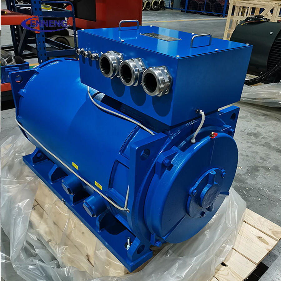
Why a Permanent Magnet Generator PMG changes the electrical loss picture
No rotor field-excitation power
In a conventional wound-field generator, electrical power is used to create the rotor magnetic field. A PMG uses permanent magnets instead. That removes the continuous field-excitation demand and the associated rotor winding losses. The benefit is straightforward: more of the mechanical torque delivered by the turbine or other prime mover can be converted into output rather than being consumed to sustain the magnetic field.
The size of that benefit depends on machine design and duty cycle, so it should not be presented as a fixed percentage. Still, the mechanism matters in waste heat recovery because net generation is often constrained by a finite and variable thermal resource. When every auxiliary load counts, eliminating an excitation subsystem simplifies the loss budget.
Efficient operation across changing speed and load
Waste heat rarely behaves like a laboratory heat source. Exhaust flow changes with production schedules, temperatures drift during start-up, and ambient conditions influence condensing equipment. As a result, an organic Rankine cycle or similar recovery system may operate below design output for meaningful periods. A well-matched Permanent Magnet Generator PMG can maintain strong efficiency under variable-speed operation when paired with appropriate rectification and inverter controls.
This is often described too broadly as “PMGs are more efficient.” More precisely, the practical advantage can be strongest when the operating profile spends time away from rated load. The selection task is therefore to compare efficiency maps at expected torque and speed points, not merely to compare the highest headline number on two data sheets.
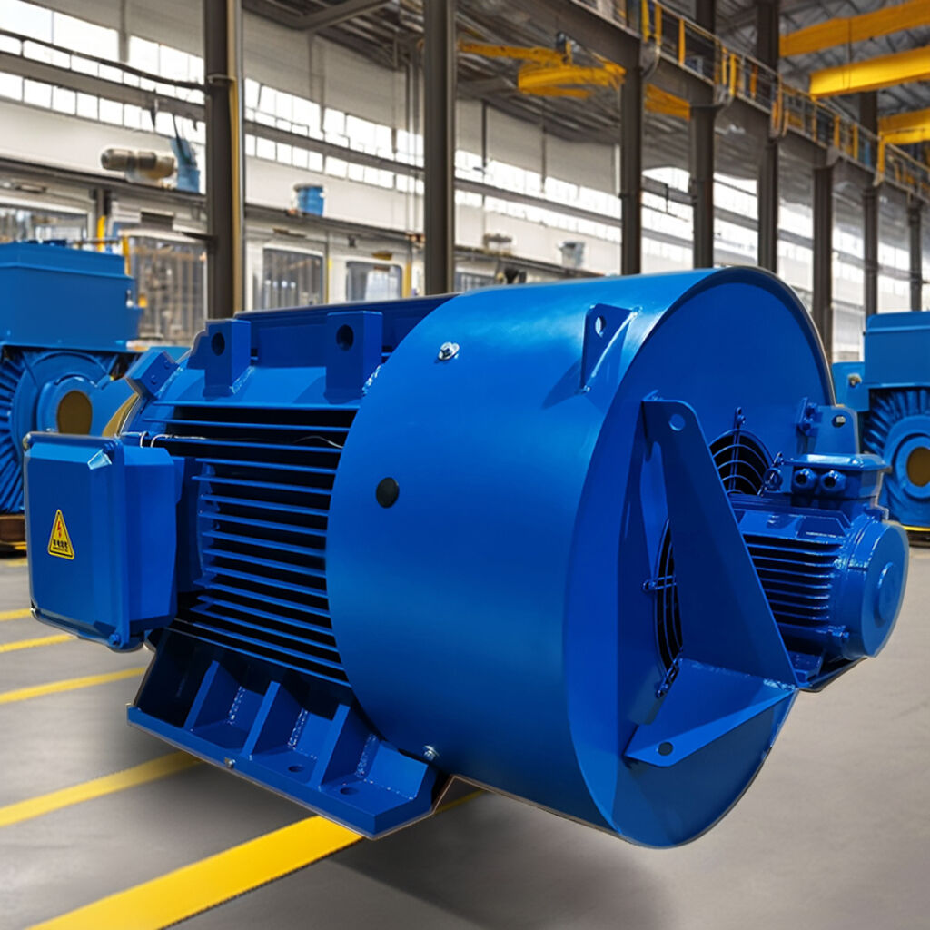
Direct coupling can reduce mechanical interfaces
Many recovery systems use a high-speed expander. If the selected generator can be matched directly to the shaft speed, the design may avoid a gearbox or reduce the mechanical complexity between expander and generator. Fewer interfaces can mean fewer sources of friction, lubrication requirements, alignment sensitivity, and mechanical loss. Direct coupling is not automatically correct: it must be checked against speed, bearing, rotor-dynamic, service, and electrical-frequency requirements. It is simply a system option worth evaluating early.
Where the efficiency gain is most relevant
A Permanent Magnet Generator PMG is usually most compelling when a project has variable thermal input, high operating hours, limited room for auxiliary equipment, or a clear need to minimize net parasitic consumption. Typical applications include exhaust-heat recovery from engines and turbines, process heat from kilns or furnaces, and remote or distributed energy sites where recovered power offsets local loads.
For teams also evaluating a Permanent Magnet Motor PMSM in pumps, fans, or process drives, the same system-level discipline applies. A high-efficiency drive can lower the electrical demand on the plant, while a PMG converts recovered shaft power into usable electricity. These are different machines with different jobs, but both should be evaluated against the actual load profile rather than only against their rated-point figures.
A practical selection workflow for waste heat projects
- Characterize the heat source. Record temperature, flow, variability, contaminants, operating hours, and planned production changes. This establishes whether the available heat can drive a recovery cycle reliably.
- Build a net-output model. Include heat-transfer losses, expander performance, generator efficiency at multiple points, converter losses, cooling or pumping loads, and transformer or cable losses. Model annual energy, not only peak kW.
- Match speed, torque, and voltage. Confirm the expander shaft-speed range and transient behavior, then select PMG poles, winding, insulation class, cooling arrangement, and power-electronics topology accordingly.
- Check the partial-load map. Ask for efficiency information at the anticipated operating points. A high rated efficiency may not produce the highest annual yield if the thermal source keeps the system at a lower fraction of nameplate output.
- Plan integration and protection. Define rectification, inverter control, grid interconnection or load-management requirements, overspeed protection, fault handling, grounding, and harmonic limits before equipment is finalized.
- Commission against measured conditions. Compare actual temperatures, shaft speed, electrical output, and auxiliary consumption with the design model. This exposes whether the loss is in the generator, the thermal train, controls, or a site interface.
Common mistakes that reduce recovered energy
|
Common mistake |
Why it hurts net output |
Better approach |
|
Using rated efficiency as the only generator criterion |
It ignores the hours spent at partial load or off-design speed. |
Compare efficiency maps at representative duty points. |
|
Ignoring converter and cooling consumption |
Gross generator output can look attractive while net export is modest. |
Track all auxiliary loads in one net-output model. |
|
Specifying the generator before defining the expander envelope |
Speed or torque mismatch can force inefficient mechanical or electrical compromises. |
Freeze the operating envelope first, then match machine and controls. |
|
Assuming a small temperature difference can be fixed electrically |
The thermodynamic limit remains upstream of the generator. |
Validate heat-source stability and cycle feasibility before optimizing electrical equipment. |
What to ask a PMG supplier before committing
Ask for more than a rated output figure. A useful technical discussion covers continuous and transient speed ranges, torque curve, efficiency map, cooling method, insulation and enclosure needs, bearing arrangement, allowable ambient conditions, rectifier or inverter compatibility, and the protection strategy. It should also establish who owns the integration boundary between expander, generator, and controls.
For custom projects, an in-house design and winding capability can make that conversation more direct because winding configuration, voltage, and mechanical interfaces can be reviewed against the application rather than forced into a generic catalog frame. The engineering objective is not to claim the largest possible PMG rating; it is to obtain predictable net kWh across the site’s real thermal duty cycle.
If you are evaluating commercial permanent magnet motors for sale and need an engineered drive solution that guarantees efficiency and longevity, ENNENG is your trusted partner.Contact ENNENG Today.Speak to our technical engineering team to receive a customised drive proposal.
- WhatsApp: +86 18562780228
- E-Mail: [email protected]
- Phone: +86 532 66000559

