
how-permanent-magnet-generator-pmg-optimizes-power-generation-output-for-industrial-wasteheat-recovery-projects, how-permanent-magnet-generator-pmg-optimizes-power-generation-output-for-industrial-wasteheat-recovery-projects, /blog
EN

2026/10/09
Industrial thermodynamic installations in cement manufacturing, glass production, and petrochemical refining release substantial quantities of thermal energy into the atmosphere. In a cement clinker production facility utilizing a dual-pressure Organic Rankine Cycle (ORC) installation, thermal exhaust gas temperatures varied continuously between 180 degrees and 320 degrees Celsius depending on kiln throughput. The original asynchronous generator experienced chronic voltage instability and rotor slip losses whenever process gas mass flow declined, shedding over twenty percent of potential electricity production. Integrating a high-coercivity Permanent Magnet Generator PMG stabilized terminal electrical parameters, maximizing kilowatt-hour conversion across volatile heat cycles. Recovering low-to-medium temperature thermal exhaust requires generation equipment capable of maintaining superior electromagnetic efficiency across erratic mechanical expander speeds.
|
Technical Metric |
Asynchronous Wound System |
ENNENG Permanent Magnet Generator PMG |
|
Electrical Conversion Efficiency |
88% - 91% |
Up to 97.4% |
|
Excitation Power Dissipation |
2.5% - 4.0% Total Capacity |
Zero (Intrinsic Magnet Excitation) |
|
Operating Voltage Coverage |
380V - 440V Rigid |
110V to 690V Unified Versatility |
|
Partial Load Efficiency (At 35% Load) |
78% - 82% |
94% - 96% |
Conventional generation equipment depends on external electrical excitation currents or mechanical brushes that introduce parasitic power consumption and recurring maintenance demands. When thermodynamic exhaust volume drops, standard wound alternators must continue drawing excitation current to sustain terminal voltage, severely penalizing net generation yields. A Permanent Magnet Generator PMG utilizes rare-earth neodymium magnetic materials that sustain a permanent excitation field across the air gap without consuming external electricity. Consequently, electrical output scales synchronously with turbine expander velocity, capturing clean electricity from previously unharvested industrial exhaust streams.
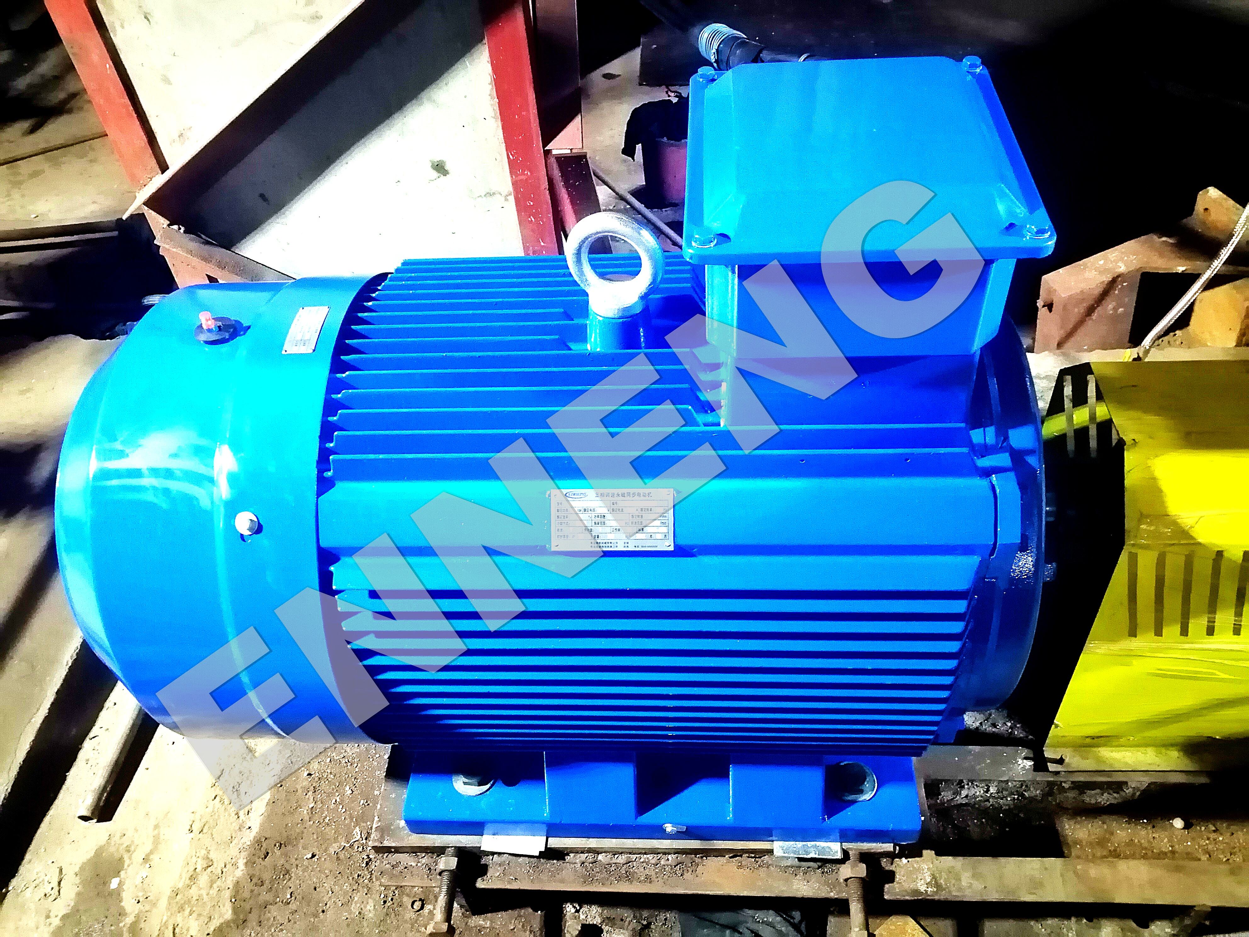
Unlike asynchronous alternators that depend on rotor slip to generate torque, a Permanent Magnet Generator PMG produces electromotive force (EMF) directly proportional to shaft rotational speed. In radial inflow expanders and screw expander skids, fluctuating vapor pressures produce rapid acceleration and deceleration. The absence of field winding inductance in a Permanent Magnet Generator PMG eliminates electromagnetic settling lag, allowing instantaneous power tracking between 20 percent and 130 percent of nominal thermal design capacity.
Operating generating machinery in close proximity to hot thermodynamic fluid loops introduces severe environmental heat. In conventional wound generators, internal rotor copper losses (I2R) elevate internal winding temperatures, threatening electrical insulation and demanding massive external cooling radiators. A Permanent Magnet Generator PMG operates with zero electrical current circulation inside the rotor assembly. This architecture lowers internal core temperatures by 15 to 25 degrees Celsius, allowing the generator to operate reliably adjacent to hot thermal oil circuits without supplemental cooling burdens.
Exporting variable-speed waste-heat power into industrial plant switchgear requires four-quadrant back-to-back power electronic converters. Traditional alternators generate pronounced harmonic distortion when forced to operate off-frequency, creating harmonic heating inside distribution transformers. The precision-skewed stator laminations and sinusoidal magnetic flux distribution of an advanced Permanent Magnet Generator PMG produce a clean sinusoidal voltage waveform, protecting intermediate DC-link capacitors and preserving inverter semiconductor longevity.
Capturing energy from volatile thermal waste streams demands durable, high-efficiency generation platforms tailored to industrial expander architectures. ENNENG manufactures advanced low-speed and high-speed synchronous permanent magnet generators engineered specifically for severe energy recovery duties. Installing an ENNENG Permanent Magnet Generator PMG elevates system thermodynamic recovery efficiency while providing uninterrupted electrical export across fluctuating manufacturing cycles.
|
Operational Characteristic |
Conventional Recovery Alternator |
ENNENG Industrial PMG |
|
Unified Industrial Power Range |
Fragmented Custom Ratings |
5kW to 5MW Platform Coverage |
|
Generation Voltage Adaptability |
Fixed Single Ratings |
110V to 690V Dynamic Matching |
|
Direct Drive Expander Match |
Multi-Stage Gearbox Required |
High-Pole Direct Shaft Coupling |
|
Operating Temperature Rise |
Class B (80K) |
Lower than 60K |
ENNENG provides a unified power capacity platform ranging from 5kW up to 5MW, accommodating complete voltage requirements from 110V to 690V. For distributed energy projects incorporating auxiliary vertical axis wind turbines, ENNENG provides specialized direct-drive generation technology spanning 1kW to 10kW, with focused engineering on 3kW, 5kW, and 10kW units.
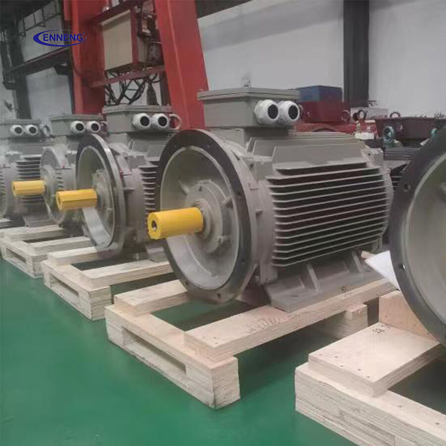
Traditional low-speed expanders require mechanical speed-increasing gearboxes to connect to standard four-pole alternators. Mechanical transmissions introduce 3 to 8 percent friction losses, continuous oil maintenance, and seal leakage hazards near hot exhaust ductwork. An ENNENG Permanent Magnet Generator PMG features high-pole-count stator architecture, enabling direct mechanical coupling to expander shafts without intermediate gearing. Eliminating gearboxes removes parasitic mechanical drag, prevents lubricating oil contamination, and maximizes net electrical output into facility microgrids.
High-temperature waste heat environments present potential risks of magnet degradation if equipment is improperly specified. ENNENG employs Class H vacuum pressure impregnation (VPI) insulation alongside rare-earth magnets enriched with dysprosium additions. Operating with a continuous temperature rise below 60K ensures that permanent magnets operate well above the knee point of their temperature-dependent B-H demagnetization curves, preserving magnetic permanence across multi-decade operating lifespans.
Industrial waste-heat recovery power stations must conform to strict global electrical and mechanical engineering criteria. Generator interconnection with factory distribution switchgear and utility grids is governed by IEEE 1547, which establishes voltage regulation parameters, frequency trip limits, and anti-islanding safety protocols.
Rotating machine thermal ratings and dielectric endurance must comply with IEC 60034-1 specifications. Total harmonic voltage distortion (THD) injected into the electrical network must adhere to IEEE 519 standards, mandating that voltage distortion remain strictly below 5 percent at the point of common coupling. A balanced Permanent Magnet Generator PMG operating with an active converter easily satisfies these harmonic criteria. Furthermore, electrical installations must comply with NFPA 70 National Electrical Code rules regarding overcurrent protection, grounding, and conductor sizing. Occupational noise exposure in generating rooms must comply with OSHA 1910.95 regulations, which enforce an 85 dBA action level.
Maximizing thermodynamic recovery output requires rigorous engineering discipline during mechanical integration and electrical commissioning.
Before finalizing generator selection, evaluate the seasonal enthalpy curves and mass flow rates of the waste-heat source. Pair the Permanent Magnet Generator PMG with an active front-end power converter rated to absorb maximum runaway expander velocities. Verify mechanical alignment between the expander shaft and generator rotor using precision laser tools, ensuring that angular and parallel runouts remain below 0.03 mm to protect bearings from radial fatigue.
Because a Permanent Magnet Generator PMG delivers variable-frequency alternating current under changing expander speeds, program the grid-tie inverter to operate in field-oriented vector control mode. Set the intermediate DC-link over-voltage protection thresholds safely above maximum expander runaway back-EMF. Incorporate dynamic braking choppers with external resistor banks to dump excess kinetic energy safely during sudden microgrid breaker trips.
Implement quarterly vibration spectral analysis conforming to ISO 10816-3 guidelines, keeping vibration velocities below 1.4 mm/s RMS. Perform annual winding insulation resistance measurements using a 1000V DC megohmmeter to detect moisture or chemical vapor contamination. Because direct-drive machines eliminate mechanical gearboxes, maintenance routines are reduced to simple bearing grease replenishment, ensuring maximum project uptime.
To review complete generator specifications and structural drawings, visit the ENNENG Products Catalog and explore system options via ENNENG Waste Heat Solutions.
For technical inquiries regarding permanent magnet generator selection or ORC integration parameters, contact ENNENG:
A: Waste heat streams fluctuate constantly in thermal energy and mass flow, forcing expanders to operate at variable speeds. An asynchronous alternator loses efficiency rapidly off-frequency and consumes continuous excitation power. A Permanent Magnet Generator PMG maintains 94 to 97 percent efficiency across a broad 25 to 120 percent operating envelope while consuming zero rotor excitation power, yielding significantly higher net megawatt-hours annually.
A: Yes. High-quality permanent magnet generators utilize specialized rare-earth neodymium magnets with high thermal coercivity, engineered to resist thermal demagnetization up to 150 or 180 degrees Celsius. Combined with Class H insulation and low operating temperature rise below 60K, the generator maintains magnetic flux stability in demanding industrial environments.
A: Direct-drive coupling mounts the expander impeller directly onto the generator shaft extension or couples them via flexible disc couplings. This removes intermediate mechanical gearboxes, eliminating 3 to 8 percent mechanical friction losses, eradicating gear oil contamination risks, and eliminating gearbox seal replacements inside hazardous thermal fluid loops.


 EN