
 EN

Industrial waste-gas heat can look like free fuel on a process diagram, then prove highly variable once temperature, flow, and production hours are measured. A Permanent Magnet Generator PMG can help a heat-to-power train turn that changing mechanical input into useful electricity, but only when the generator is matched to the expander, controls, and site duty cycle. The useful question is not whether a Permanent Magnet Generator PMG has a favorable nameplate efficiency. It is whether its electrical behavior improves net output across the conditions the project will actually see.
From an engineering perspective, the starting point is the load profile. Waste heat is commonly transferred to a working fluid that drives a turbine or expander, which then drives a generator. In industrial waste-gas applications, source temperature alone is not enough: mass flow, pressure, composition, fouling, bypass events, and production schedules all influence the shaft power reaching the generator. That is why a Permanent Magnet Generator PMG should be selected as part of a conversion train rather than as an isolated electrical component.
Start with the heat source, not the generator nameplate
The shift that changes a specification is realizing that peak generator output matters only if the waste-gas stream can supply corresponding shaft power for meaningful operating hours. A site survey should log inlet and outlet temperatures, gas flow, allowable pressure drop, heat-exchanger approach limits, contaminant risks, and seasonal or batch-process variation. These inputs define the expander speed and torque envelope; that envelope defines what the Permanent Magnet Generator PMG must accept.
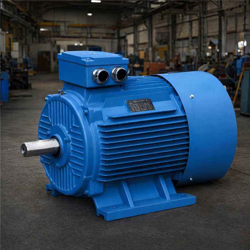
For example, a stable high-temperature exhaust stream may support a relatively narrow operating band. A furnace line with cyclic production may require a much broader band and more careful start/stop logic. Once ambient temperature and cooling conditions are included, a Permanent Magnet Generator PMG nameplate rating can look quite different from the continuous rating the project should plan around. This is not a weakness of the machine; it is a reminder that electrical sizing must follow the available thermal resource.
Why the PMG topology can improve conversion performance
A Permanent Magnet Generator PMG uses rotor magnets instead of a separately excited rotor field. Removing rotor excitation losses can support efficient conversion, especially when shaft speed and load vary. More precisely, it can reduce one source of electrical loss; the project still has stator losses, converter losses, bearing losses, cooling demand, and turbine or expander losses to manage.
That distinction matters in waste-heat recovery. When recovered heat falls, the expander may move away from its design point. A well-matched Permanent Magnet Generator PMG, paired with suitable power electronics, can allow variable-speed operation rather than forcing the mechanical system to remain at one grid-synchronous speed. The controls can then condition the variable-frequency output for the site bus, storage system, or grid interface while keeping the rotating train within permitted torque and thermal limits.
- Reduced excitation demand: A Permanent Magnet Generator PMG does not need a separate rotor excitation supply.
- Variable-speed compatibility: The generator and converter can be specified around the expander’s usable speed range.
- Responsive voltage control: A converter can regulate delivered voltage and frequency even while mechanical speed changes.
- Lower mechanical complexity in some layouts: Direct coupling may reduce dependence on a speed-increasing gearbox when torque and speed are appropriate.
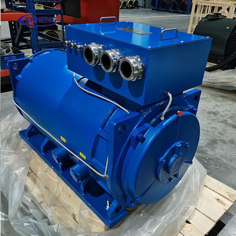
Match speed, torque, voltage, and converter capacity as one system
The main design task is to map the expander’s torque-speed curve against the Permanent Magnet Generator PMG efficiency map and the converter’s operating window. Oversizing a generator can leave it running lightly loaded for long periods. Undersizing it can create thermal stress, torque limiting, or frequent curtailment when waste heat is available. Neither outcome is an optimization.
Ask the engineering team to evaluate the following points together:
- Mechanical envelope: minimum, normal, and maximum shaft speed; transient acceleration; torsional behavior; and overspeed protection.
- Electrical envelope: rated and peak torque, winding temperature rise, insulation class, voltage range, and allowable current.
- Power electronics: rectifier/inverter topology, harmonic performance, DC-link sizing, grid-code obligations where relevant, and fault ride-through logic.
- Parasitic loads: pumps, fans, cooling equipment, controls, and transformer losses that reduce net exported power.
A Permanent Magnet Generator PMG cannot compensate for an expander that is poorly matched to the heat source, but it can preserve more usable output when the mechanical input is variable and controls are designed around that variability.
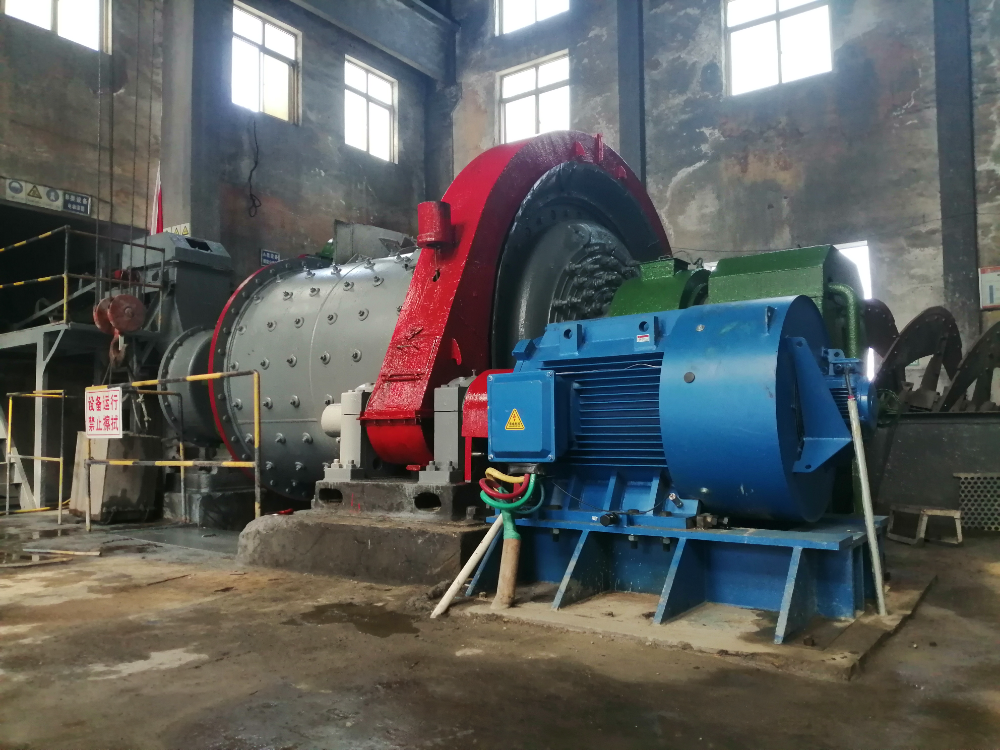
Use control logic to protect both output and equipment life
Heat-recovery performance is often lost during transitions rather than steady operation. Startup heating, process interruptions, changes in gas composition, and heat-exchanger fouling can alter shaft input quickly. The Permanent Magnet Generator PMG control strategy should therefore include speed limits, torque limits, generator temperature monitoring, DC-bus protection, and controlled shutdown thresholds.
Teams can be tempted to pursue every kilowatt during a short high-heat event. In practice, a stable operating policy may create more annual value if it avoids repeated thermal cycling, converter trips, or unplanned maintenance. A Permanent Magnet Generator PMG specification should state continuous and intermittent duty explicitly, along with the cooling arrangement and permitted ambient conditions.
Do not confuse a PMG with a Permanent Magnet Motor PMSM
A Permanent Magnet Motor PMSM and a Permanent Magnet Generator PMG share magnetic-machine principles, but their project roles are different. A PMSM consumes electrical power to create mechanical motion; the generator converts mechanical shaft power into electrical power. In a waste-gas heat project, a Permanent Magnet Motor PMSM may still appear in auxiliary pumps, fans, or compressors. Coordinating those auxiliary loads with the Permanent Magnet Generator PMG is useful because auxiliaries determine the project’s net electrical output, not just its gross generation.
A practical commissioning sequence
Commissioning should verify the energy path from gas stream to delivered electricity. First, validate heat-source measurements under representative production conditions. Next, confirm expander speed, torque, vibration, and control stability. Then test the Permanent Magnet Generator PMG across staged loads while recording winding temperature, converter behavior, and output quality. Finally, calculate net power after auxiliaries rather than reporting generator terminals alone.
For project teams, the useful procurement request is not simply “high-efficiency PMG.” It is a documented operating envelope: heat-source assumptions, shaft-speed range, torque curve, voltage and converter requirements, cooling conditions, protection functions, test acceptance criteria, and interface responsibilities. A supplier with permanent-magnet motor and generator design capability can help review these inputs, but final performance must be verified against the site’s actual process data.
Conclusion: optimize the operating window, not one catalog number
A Permanent Magnet Generator PMG can improve the electrical side of an industrial waste-gas heat utilization project by avoiding rotor excitation losses and working effectively with variable-speed power conversion. The strongest results come from treating the Permanent Magnet Generator PMG, expander, converter, cooling system, and auxiliaries as one controlled system. Characterize the heat source first, select the operating envelope second, and judge success by stable net power over the real duty cycle.
The ENNENG Customisation Advantage
No two industrial facilities share the same spatial or mechanical constraints. ENNENG stands out because we do not just supply off-the-shelf catalogue products; we specialise in delivering a tailor-made permanent magnet motor tailored to your specific application .
Supported by our elite R&D team consisting of engineers from the National Rare Earth Permanent Magnet Engineering Centre, and backed by dozens of patents, we customise high-voltage (6kV/10kV) and low-voltage (380V/660V/1140V) solutions to match your existing footprint. From water treatment facilities and oil wells to explosion-proof mining environments, we deliver optimal performance where general-purpose motors fail .
If you are evaluating commercial permanent magnet motors for sale and need an engineered drive solution that guarantees efficiency and longevity, ENNENG is your trusted partner.Contact ENNENG Today.Speak to our technical engineering team to receive a customised drive proposal.
- WhatsApp: +86 18562780228
- E-Mail: [email protected]
- Phone: +86 532 66000559

