
 EN

How Permanent Magnet Generator PMG Reduces Unit Volume for Industrial Waste-Heat-Utilization Power Generation Systems
Industrial waste-heat projects rarely fail because the thermodynamic concept is difficult. They more often run into a practical constraint: the available space around a kiln, compressor, furnace, engine, or process line is already occupied by ducts, access routes, piping, and maintenance clearances. A Permanent Magnet Generator PMG can help a heat-to-power package fit that reality because it removes part of the excitation hardware that a conventional wound-field generator needs. That does not make every package small by default. It changes where the designer can save volume and where the trade-offs need attention.
As an engineer reviewing rotating-equipment layouts, I start with the duty cycle and the installation envelope rather than a nameplate rating. For a waste-heat system, the useful question is not simply whether a Permanent Magnet Generator PMG is compact. It is whether the generator, expander or turbine, coupling, controls, cooling, and service access can be arranged as one maintainable power module.
Why generator volume matters in a waste-heat power module
A typical waste-heat-utilization system has more than a heat exchanger and a generator. It may include a working-fluid loop, an expander, lubrication equipment, electrical conversion equipment, a cooling circuit, isolation valves, instrumentation, and structural steel. The generator is not necessarily the largest item, yet it can force a larger skid if its excitation equipment, brush gear, coupling length, or separate control interfaces spread the package apart.
This is where a Permanent Magnet Generator PMG changes the layout conversation. Its rotor magnetic field is supplied by permanent magnets rather than by a rotor field winding fed through a dedicated excitation arrangement. In broad engineering terms, fewer excitation-related components can mean fewer interfaces to package, wire, cool, protect, and leave accessible for maintenance. The gain is often most useful at the edges of the machine: the auxiliary cabinets, routing paths, service zones, and mechanical allowances that accumulate around a conventional arrangement.
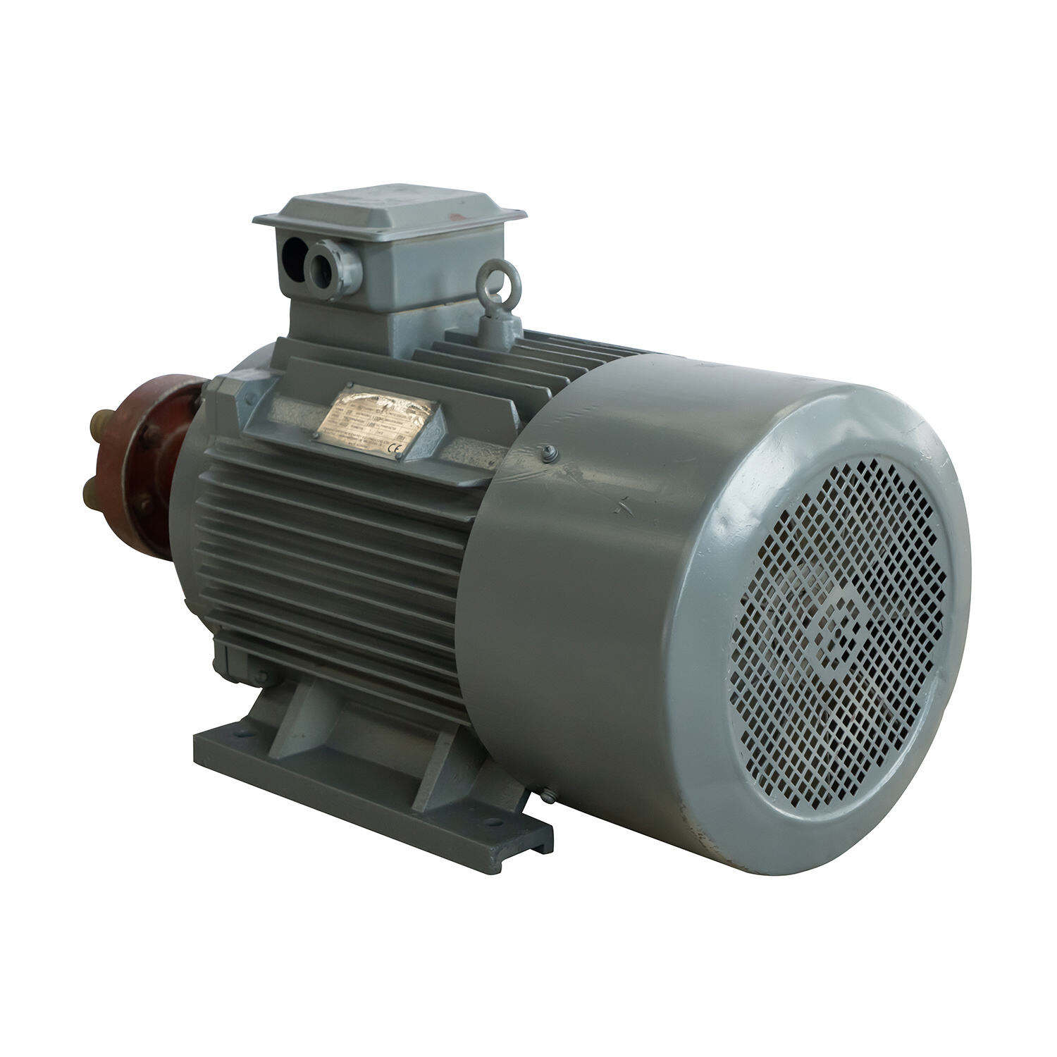
Three ways a PMG can reduce installed volume
1. It removes the rotor-excitation chain
A wound-field generator needs a way to establish and regulate rotor field current. Depending on the design, that involves an exciter, rectifier assembly, brushless rotating parts, or other excitation-supporting equipment. A Permanent Magnet Generator PMG does not need rotor current to create its primary field. That does not eliminate all electronics—the system still needs protection, voltage handling, and often power conversion—but it can simplify the generator-side architecture.
The physical benefit is not just one missing box. It is the reduction of brackets, cables, terminations, rotating interfaces, inspection access, and protective separation associated with those items. In a constrained retrofit, avoiding even one extra service-side envelope can determine whether the skid fits beside existing process equipment.
2. It supports closer integration with the prime mover
Waste-heat recovery often uses a variable-speed expander or turbine. A Permanent Magnet Generator PMG can be paired directly with that rotating machine when the mechanical and electrical design supports it. Direct integration can reduce the number of shafts, couplings, guards, and gearbox-related interfaces in comparison with an arrangement that needs speed conversion. It also gives the package designer more freedom to place the machine axis, bearing supports, and converter enclosure around the actual site envelope.
The important correction is that direct drive is not automatically the smallest choice. A low-speed machine may require a larger diameter to produce the required torque, while a high-speed machine can introduce bearing, rotor-containment, vibration, and cooling requirements. The compact option is the configuration that reduces the total installed envelope after those requirements are included—not the one with the shortest shaft alone.
3. It can consolidate electrical conversion around a variable-speed system
Many heat-to-power systems experience changing heat-source temperature, flow, or operating point. With a Permanent Magnet Generator PMG, designers commonly treat the generator and power electronics as an integrated variable-speed electrical subsystem. When the converter, protection, sensing, and cooling interfaces are designed together, cabling and panel placement can be more deliberate than in a collection of separately specified components.
This is a packaging opportunity, not a promise that the control cabinet disappears. The converter still needs adequate ventilation, electromagnetic compatibility measures, safe isolation, and accessible service space. Its size also depends on voltage, current, harmonics requirements, enclosure rating, and the site’s grid or load interface. A compact generator paired with an oversized or poorly placed converter does not create a compact plant.
Frame size versus full-unit volume: do not confuse them
It is tempting to compare only generator dimensions. That misses the reason a Permanent Magnet Generator PMG is relevant to waste-heat utilization. The project team should assess at least four envelopes:
- Machine envelope: stator, rotor, housing, terminal box, bearings, and mounting feet.
- Mechanical integration envelope: coupling or integrated shaft, guards, alignment allowance, lifting path, and vibration isolation.
- Electrical envelope: converter, switchgear, sensors, cable bends, grounding, and cooling provisions.
- Maintenance envelope: access for inspection, bearing service, connector removal, rotor handling, and safe isolation.
The useful comparison is therefore skid length × width × height plus required service clearance. A Permanent Magnet Generator PMG can reduce the hardware count inside that boundary, but the site layout must show that the freed volume is not immediately consumed by another system requirement.
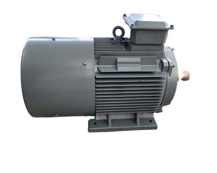
Where compactness helps most in industrial retrofits
The strongest use case is usually a retrofit with a defined thermal source and a tight installation route. For example, a plant may have adequate heat in exhaust gas, hot oil, or process cooling water but little unused floor area. A package that combines the expander and generator more closely can shorten the mechanical train and make it easier to install the module in a service bay or on a structural platform.
A Permanent Magnet Generator PMG can also make sense where maintenance access is expensive. Removing excitation-related wear components can reduce the number of tasks that require opening the machine-side assembly. That is a lifecycle advantage rather than a claim that maintenance becomes unnecessary. Cooling passages, bearings, converter components, insulation condition, alignment, and protection settings still need a planned inspection routine.
The related term Permanent Magnet Motor PMSM is useful in this discussion because it describes the same permanent-magnet field principle on the motor side. In a heat-recovery package, a PMG generates power from the expander; a Permanent Magnet Motor PMSM consumes power to drive a load. They are not interchangeable selections, yet the shared electromagnetic concept helps explain why permanent-magnet machines can offer a high power-density route when the complete system is engineered for it.
What must be checked before specifying a PMG
- Map the real operating window. Record heat-source temperature, flow variation, startup behavior, ambient conditions, and expected turndown. The generator rating must match the prime mover across that window, not only at a design-point calculation.
- Define the speed strategy. Decide whether the expander and Permanent Magnet Generator PMG will be directly integrated, coupled, or geared. Evaluate torsional behavior, rotor dynamics, and fault response before treating direct drive as a space-saving assumption.
- Draw the service envelope early. Place cable entries, converter doors, lifting points, filters, and isolation devices in the 3D layout. A compact housing does not help if technicians cannot remove a connector or inspect a bearing.
- Specify thermal paths. Confirm how generator losses and converter losses leave the enclosure. At hotter sites, ambient-temperature derating can change both machine selection and cabinet volume.
- Review system protection. Fault isolation, overspeed response, grounding, insulation monitoring, and grid/load behavior should be resolved as a package-level design task.
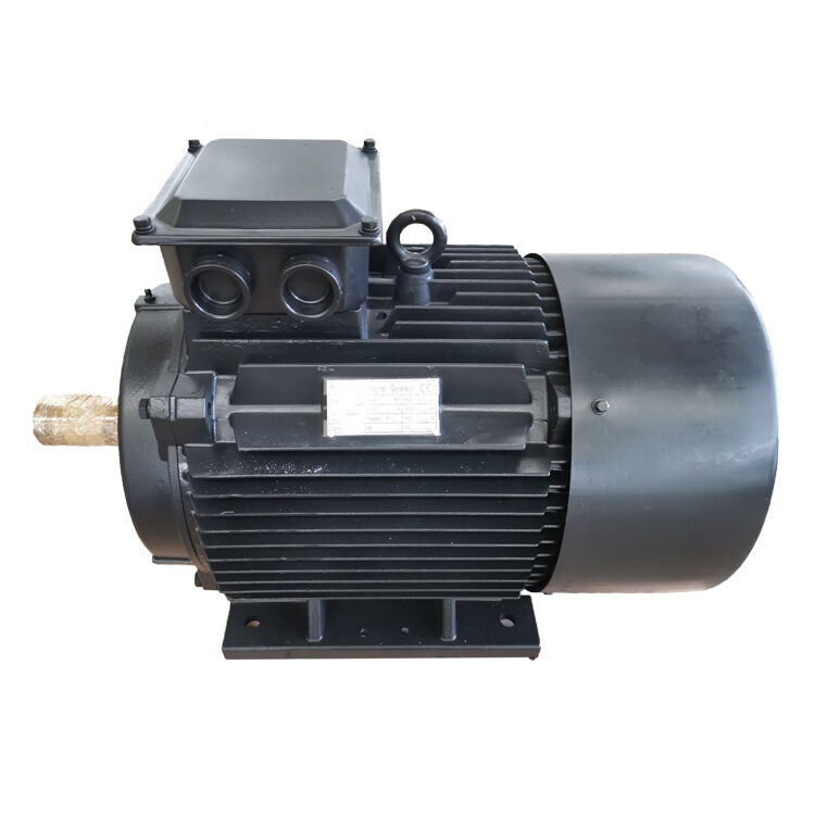
The ENNENG Customisation Advantage
If you are evaluating commercial permanent magnet motors for sale and need an engineered drive solution that guarantees efficiency and longevity, ENNENG is your trusted partner.Contact ENNENG Today.Speak to our technical engineering team to receive a customised drive proposal.
- WhatsApp: +86 18562780228
- E-Mail: [email protected]
- Phone: +86 532 66000559
A practical decision framework
There is no universally smallest generator topology. If your priority is a shorter mechanical train and fewer excitation-related interfaces, evaluate a Permanent Magnet Generator PMG early. If the heat source is highly variable, evaluate the generator and converter together rather than treating the electrical system as an afterthought. If the site has difficult maintenance access, put service clearances on the layout before releasing the skid design.
The purchase decision usually starts with equipment cost, but the number that matters over the operating life is the cost of keeping a constrained installation available. For industrial waste-heat utilization, the most suitable compact design converts recovered heat reliably while leaving room to commission, inspect, and repair the equipment safely. A well-integrated Permanent Magnet Generator PMG can reduce unit volume by simplifying the machine-side architecture; the final benefit depends on disciplined mechanical, electrical, thermal, and maintenance integration.

