
 EN

Municipal wastewater treatment facilities operating continuous raw sewage lift stations 8,400 hours annually often face severe footprint restrictions in deep underground pump vaults. Plant engineers deploying high-efficiency pumping equipment in these congested galleries must carefully evaluate physical boundaries, shaft orientations, and thermal dissipation paths before selecting a drive configuration. Upgrading to an ultra-premium Centrifugal Pump Motor IE5 maximizes hydraulic efficiency and slashes energy expenses, but capturing these benefits requires matching the motor mounting arrangement to verified site space conditions.
Spatial Constraints and Mechanical Loading in Pumping Galleries
Industrial pumping bays rarely provide unlimited floor space or ideal overhead clearance for equipment handling. Selecting an effective Energy Saving Motor Solution requires facility teams to map three-dimensional spatial limitations—floor area, vertical overhead access, and axial clearance—before finalizing equipment purchase orders. A Centrifugal Pump Motor IE5 delivers superior power density compared to legacy induction units, yet physical installation geometry directly governs operational reliability.
Floor Space Footprint and Baseplate Deflection Hazards
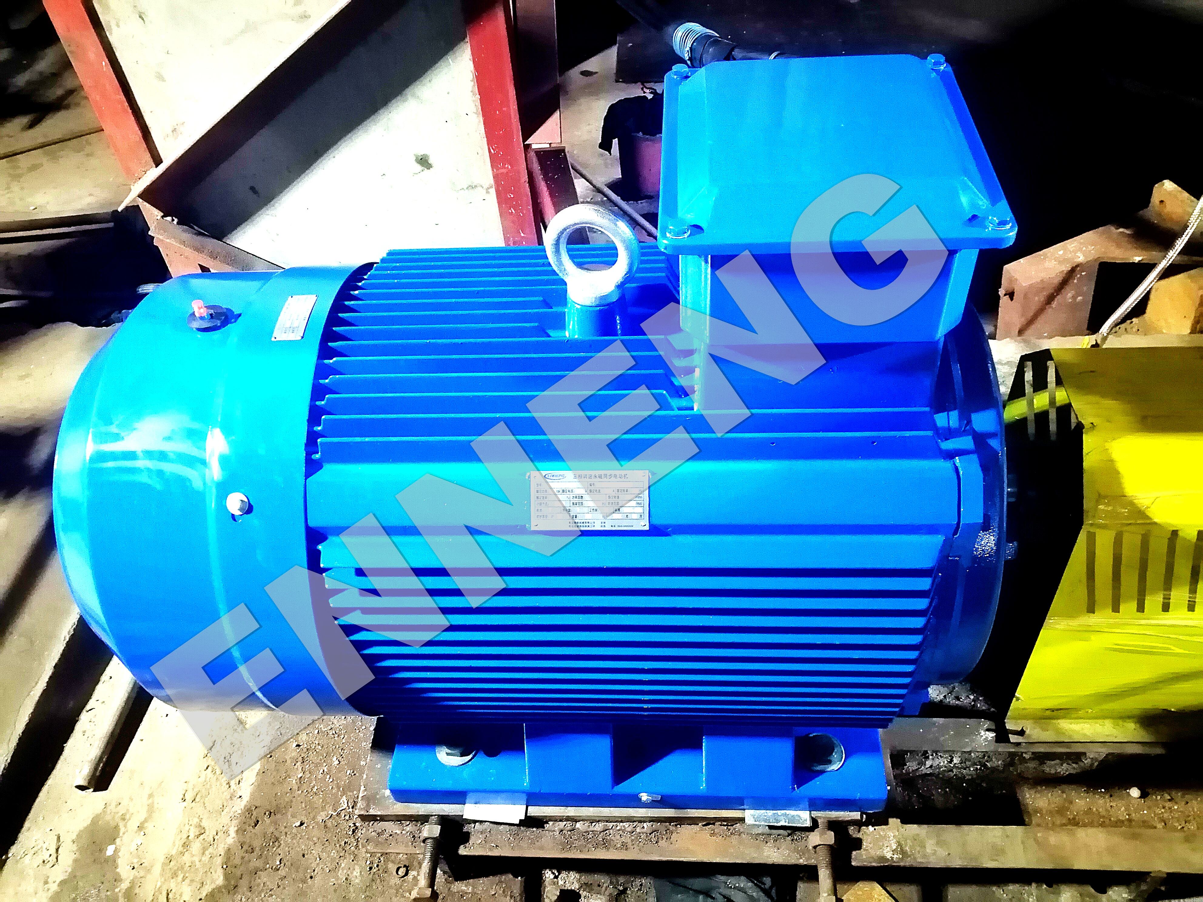
In crowded utility basements and chemical skids, available floor space often dictates whether a pump set can utilize a traditional horizontal footprint. Positioning a horizontal Centrifugal Pump Motor IE5 requires sufficient floor length for the pump casing, flexible coupling guard, motor frame, and non-drive-end maintenance access. Installing heavy machinery onto undersized or corroded steel skids provokes structural deflection under dynamic torque loads.
Thermal Ventilation Clearances and Inverter Proximity
High-efficiency electric machinery produces significantly lower internal heat losses than older motors, yet thermal management remains vital in restricted mechanical rooms. A totally enclosed fan-cooled Centrifugal Pump Motor IE5 requires an unobstructed clearance of at least 300 millimeters at the fan cowl intake. Placing the non-drive end flush against a concrete wall or structural column restricts convective airflow, elevating internal winding temperatures and accelerating insulation breakdown.
Evaluating IEC 60034-7 Mounting Codes for IE5 Pump Drives
Standard IEC 60034-7 codifies motor mounting arrangements into standardized International Mounting (IM) designations that define shaft orientation, frame support methods, and drive-end flange designs. Selecting the proper code ensures that a Centrifugal Pump Motor IE5 fits the host pump casing without requiring expensive on-site structural modifications.
Horizontal Foot-Mounted IM B3 and Dual-Support IM B35 Modes
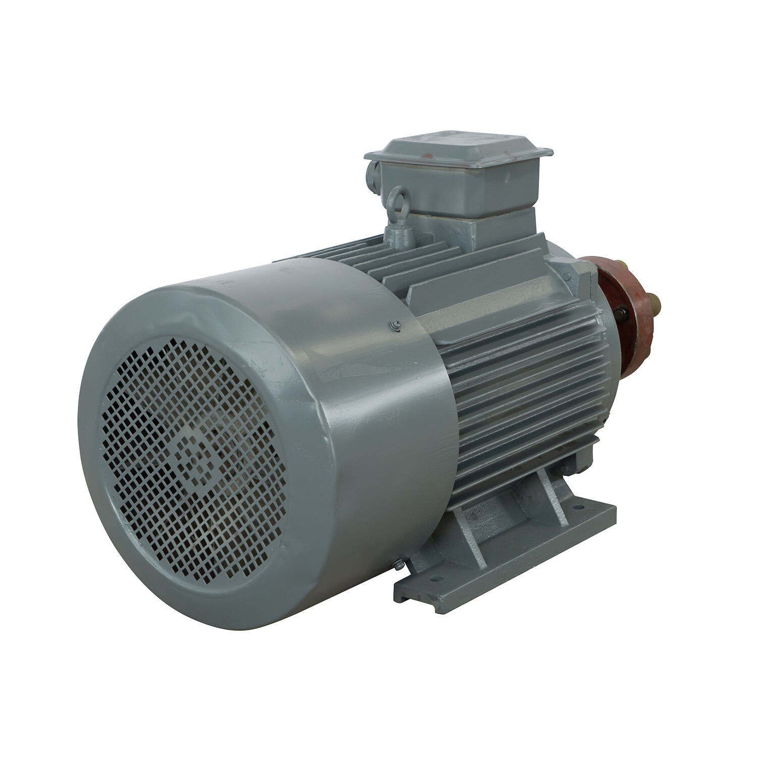
The IM B3 designation represents the most common horizontal mounting mode in industrial facilities. An IM B3 Centrifugal Pump Motor IE5 features four rigid mounting feet bolted to a horizontal foundation or machined steel skid. This arrangement provides excellent mechanical stability, simplifies laser coupling alignment, and ensures straightforward access to the junction box and bearing lubrication points. Where floor space is ample, IM B3 serves as the standard baseline for horizontal split-case and end-suction pumps.
For installations where skid layouts remain tentative during procurement, specifying an IM B35 configuration offers valuable installation flexibility. An IM B35 Centrifugal Pump Motor IE5 incorporates both rigid mounting feet and a precision-machined D-flange on the drive-end shield. This dual-support design allows maintenance personnel to secure the motor via foot bolts, flange connections, or both, ensuring seamless mechanical adaptation during plant floor modifications.
Flange-Mounted IM B5 and Face-Mounted IM B14 Compact Configurations
When plant floor space is severely constrained, eliminating the intermediate baseplate recovers between 150 and 400 millimeters of axial length. An IM B5 Centrifugal Pump Motor IE5 bolts directly to the pump intermediate bracket via an oversized flange, creating a rigid, close-coupled pump package. This close-coupled arrangement eliminates separate pump bearings, eliminates coupling alignment tasks, and prevents baseplate deflection issues in compact heating and cooling skids.
For smaller pumping units, the IM B14 mounting mode utilizes a smaller face-mounted flange with threaded holes tapped directly into the front end-shield. Specifying an IM B14 Centrifugal Pump Motor IE5 suits auxiliary lubricating pumps, chemical dosing skids, and machine tool coolant systems where reduced radial dimensions are required to prevent interference with adjacent piping runs.
|
Mounting Code (IEC 60034-7) |
Mechanical Support Method |
Spatial Footprint Characteristic |
Primary Industrial Pump Scene |
|
IM B3 |
Four-foot horizontal base mounting |
Requires full floor length for skid |
Large horizontal split-case water pumps |
|
IM B5 |
Drive-end large flange (close-coupled) |
Compact axial length, no motor baseplate |
Space-constrained HVAC and booster skids |
|
IM B14 |
Face-mounted small tapped flange |
Ultra-compact radial and axial envelope |
Auxiliary chemical dosing and oil pumps |
|
IM B35 |
Dual foot and large flange support |
Adaptable horizontal configuration |
High-vibration slurry and slurry feed lines |
|
IM V1 |
Vertical flange mounting (shaft down) |
Minimal floor area, requires vertical height |
Deep-well turbine and vertical inline pumps |
Vertical Shaft IM V1 Architecture for Inline Centrifugal Pumping
Vertical inline centrifugal pumps and multi-stage sump pumps demand a vertical motor orientation to minimize facility footprint. An IM V1 Centrifugal Pump Motor IE5 mounts vertically above the pump head with the drive-end shaft pointing downward. This vertical installation mode reduces required floor area by up to seventy percent compared to horizontal skids, making it the ideal choice for offshore platforms, shipboard machinery rooms, and municipal pump vaults.
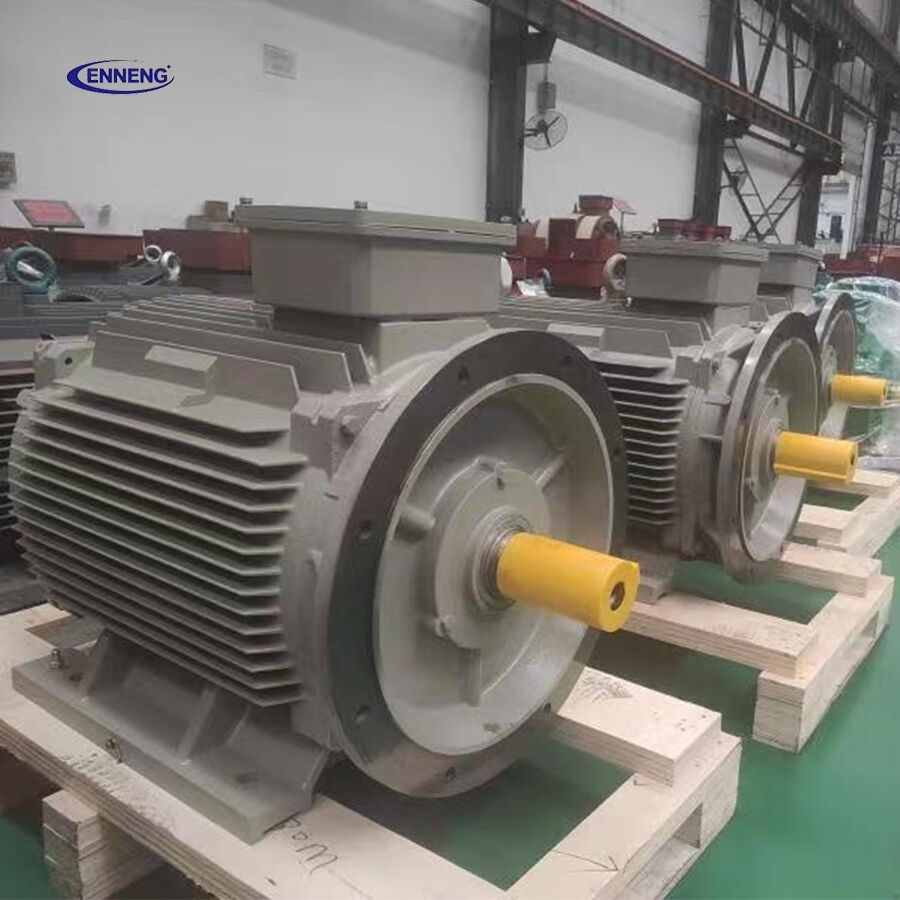
However, operating a Permanent Magnet Motor PMSM in an IM V1 orientation requires specialized bearing engineering. The motor must incorporate angular contact or deep-groove ball bearings capable of supporting continuous downward gravitational forces from the rotor assembly and dynamic hydraulic thrust loads. ENNENG motor products are engineered across unified voltage ratings from 110V to 690V and power ranges from 5kW to 5MW, providing reinforced bearing systems and protective drip-proof cowls for dependable vertical service. For remote off-grid monitoring and coastal telemetry, ENNENG also delivers vertical axis wind turbine systems rated from 1kW to 10kW, emphasizing 3kW, 5kW, and 10kW platforms to ensure reliable utility generation.
Engineering Standards, Vibration Control, and Mechanical Maintenance
Industrial pump installations must adhere strictly to established international engineering standards and workplace safety regulations. Motor vibration severity must comply with ISO 10816-3 evaluation limits, ensuring that dynamic oscillation remains within acceptable boundaries to prevent mechanical seal failure. Drive efficiency verification must satisfy IEC TS 60034-30-2 criteria for converter-fed variable-speed machines, verifying the Ultra-Premium performance delivered by a modern Centrifugal Pump Motor IE5. Implementing high-efficiency pumping infrastructure supports corporate carbon reduction goals governed by ISO 50001 energy management frameworks.
Long-term mechanical reliability requires disciplined preventive maintenance protocols. Technicians must conduct precision laser alignment during initial installation of an IM B3 Centrifugal Pump Motor IE5, maintaining angular and parallel tolerances within 0.03 millimeters. Winding insulation resistance and polarization index values should be checked annually using a calibrated megohmmeter per IEEE 43 guidelines. Keeping cooling fan cowls and frame heat dissipation fins clear of industrial dust and sludge ensures that an IE4/IE5 Efficiency Motor maintains peak thermal performance over decades of operation.
Engineering Consultation and Motor Selection Inquiries
Selecting the ideal mounting configuration for a Centrifugal Pump Motor IE5 requires analyzing piping geometry, floor loading limits, and continuous hydraulic duty profiles. Modernizing plant pumping assets with advanced drive technology reduces electrical power costs, minimizes maintenance downtime, and optimizes facility space utilization. Partnering with a dedicated High Efficiency Motor Supplier guarantees proper mechanical flange engineering, verified bearing thrust capacity, and complete drive integration support. Contact the technical team today to evaluate site space parameters and receive tailored equipment recommendations.
- WhatsApp: +86 18562780228
- E-Mail: [email protected]
- Phone: +86 532 66000559
FAQ
Q: What spatial clearance is required around a centrifugal pump motor IE5 for effective ventilation?
A: A totally enclosed fan-cooled Centrifugal Pump Motor IE5 requires an unobstructed clearance of at least 300 millimeters at the non-drive end fan cowl. Maintaining this clearance ensures that the external cooling fan draws adequate ambient air volume to dissipate stator heat. In restricted pump rooms, blocking the fan intake elevates internal winding temperatures and risks triggering thermal overload protections.
Q: Why does a vertical IM V1 centrifugal pump motor IE5 require specialized bearings?
A: In a vertical IM V1 orientation, the motor bearings must support the static gravitational weight of the permanent magnet rotor in addition to downward or upward hydraulic thrust loads generated by the pump impeller. Standard horizontal ball bearings can experience premature brinelling and fatigue under continuous axial loading. Specifying reinforced angular contact bearings or preloaded thrust bearings ensures dependable vertical operation.
Q: When should an enterprise select an IM B5 close-coupled flange mounting over IM B3?
A: An IM B5 close-coupled mounting arrangement is ideal for installations with constrained floor area or where skid fabrication costs must be minimized. Bolting the Centrifugal Pump Motor IE5 directly to the pump housing eliminates the intermediate baseplate and flexible coupling, shortening total axial length by up to 400 millimeters while eliminating time-consuming shaft alignment procedures during installation.

