
what-commissioning-guidelines-should-follow-for-textile-machinery-pm-motor-after-field-installation-work, what-commissioning-guidelines-should-follow-for-textile-machinery-pm-motor-after-field-installation-work, /blog
EN

2026/10/09
High-speed textile production environments demand extreme rotational precision, thermal stability, and synchronized motion control across thousands of spinning spindles. In a high-capacity compact yarn spinning mill operating continuous ring spinning frames, an uncalibrated motor installation produced severe rotational speed fluctuations and periodic motor stall trips across several spinning banks. Quality inspection immediately revealed widespread yarn breakage and uneven yarn count deviations that ruined several production batches. Technical analysis traced the root cause to improper inverter autotuning, unshielded feedback cabling, and mechanical soft foot during motor installation. Commissioning a high-performance Textile Machinery PM Motor requires disciplined adherence to standardized electrical, mechanical, and dynamic tuning procedures to unlock flawless production synchronization.
|
Commissioning Parameter |
Suboptimal Setting |
Production Defect |
Rectification Protocol |
|
Inverter Current Loop Gain |
Sluggish PI Response |
Dynamic yarn tension variations |
High-speed dynamic loop autotuning |
|
Resolver / Encoder Offset |
Angular Offset Error (Over 5 deg) |
High torque ripple, acoustic chatter |
Magnetic pole zero-angle identification |
|
Baseplate Coplanarity |
Soft Foot Deflection (Over 0.05 mm) |
Elevated frame vibration trips |
Precision stainless steel shimming |
|
Thermal Limit Parameters |
Incorrect Sensor Type Mapping |
False thermal overload trips |
Calibrated PT100 / PTC sensor scaling |
Modern textile machinery, including draw-texturing machines, circular knitting equipment, and continuous spinning frames, relies on precise velocity control to prevent uneven yarn elongation. Standard induction motors suffer from dynamic slip, meaning rotational speed fluctuates whenever yarn package diameters increase or mechanical friction varies. Upgrading to a Textile Machinery PM Motor eliminates rotor slip entirely because permanent magnet synchronous technology locks shaft rotation directly to the inverter output frequency. However, realizing this precise synchronization depends entirely on disciplined commissioning procedures.

In multi-spindle textile machinery, dozens of synchronized motors must accelerate, run, and decelerate in absolute mechanical harmony. Any rotational velocity discrepancy between drafting rollers and winding spindles causes instant yarn snarling or breakage. A Textile Machinery PM Motor delivers true synchronous speed control without slip, maintaining identical rotational velocity across all axes regardless of individual spindle friction variations. Commissioning engineers must verify that inverter master-follower synchronization buses communicate with microsecond timing.
Textile processing rooms operate under elevated ambient temperatures and produce vast quantities of airborne fly lint and combustible cotton dust. If cooling airways become blocked, electric motors can overheat rapidly. Specialized Textile Machinery PM Motor designs feature streamlined, non-ventilated (TENV) or totally enclosed fan-cooled (TEFC) carcasses with anti-clogging surface contours. Commissioning protocols must ensure smooth airflow passages and verify thermal sensor trip parameters inside drive controllers.
Textile spinning machinery experiences high starting inertia when spinning bobbins are fully loaded. Attempting to accelerate high-inertia spindle banks without properly calibrated drive starting algorithms causes inverter overcurrent trips or yarn breakage. A Textile Machinery PM Motor paired with an intelligent drive develops high starting torque without drawing excessive inrush currents, guaranteeing smooth yarn tension control from zero speed up to maximum operating velocities.
Delivering flawless yarn quality requires motor drive technology engineered for exceptional rotational smoothness and continuous thermal stability. ENNENG manufactures high-precision permanent magnet synchronous motors specifically developed for demanding textile machinery applications. Integrating an ENNENG Textile Machinery PM Motor into production lines delivers energy savings of 15 to 35 percent while ensuring absolute speed synchronization.
|
Technical Parameter |
Standard Asynchronous Drive |
ENNENG Textile Machinery PM Motor |
|
Rotational Speed Slip |
2% — 5% Dynamic Slip |
Absolute Zero Slip (0%) |
|
Unified Operating Voltage Span |
380V — 440V Rigid |
110V to 690V Versatility |
|
Total Power Capability Matrix |
Segmented Small Frames |
5kW to 5MW Unified Platform |
|
Operational Temperature Rise |
Class B (80K) |
Lower than 60K |
The unified manufacturing matrix offered by ENNENG covers broad power ratings from 5kW up to 5MW, with versatile voltage capabilities spanning 110V to 690V. Operating with an internal temperature rise below 60K protects winding insulation and prevents localized heating from melting synthetic yarn fibers.
Torque pulsations inside electric motors produce microscopic rotational speed variations that cause visible barree defects in knitted fabrics. ENNENG textile motors utilize proprietary stator slot skewing and optimized magnet arc geometry to reduce cogging torque below 0.5 percent of nominal torque. This smooth electromagnetic torque delivery ensures uniform yarn tension during sensitive spinning cycles.
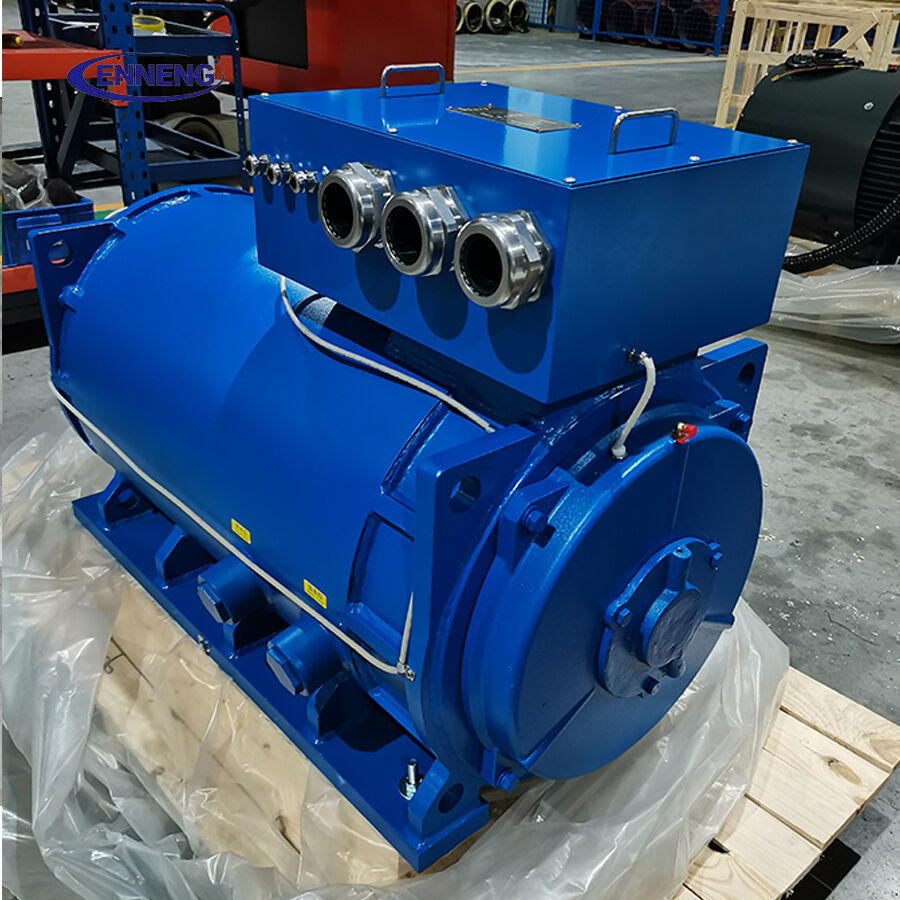
Textile machines pack multiple motorized rollers into tight structural frames. ENNENG permanent magnet synchronous motors deliver exceptionally high torque and power density, fitting into footprints that are thirty percent smaller than traditional induction motors. This compact form factor simplifies retrofits on compact spinning frames and draw-twist machines.
Textile machinery electrical installations and commissioning must comply with strict international industrial codes. Machine electrical safety and control architecture must satisfy IEC 60204-1, which governs the electrical equipment of industrial machines, including emergency stop categorization and conductor protection.
Rotational vibration verification following installation must adhere to ISO 10816-3 Zone A guidelines, confirming vibration velocities remain below 1.4 mm/s RMS. Electrical motor thermal ratings and efficiency testing must comply with IEC 60034-1 and IEC 60034-2-1. Furthermore, because textile processing facilities contain combustible cotton fly fibers, electrical enclosures and cable entries must comply with NFPA 654 and NFPA 70 Class II, Division 1 or Division 2 combustible dust safety regulations. Deploying a sealed Textile Machinery PM Motor conforming to IP55, IP65, or IP66 standards prevents dust accumulation from causing internal electrical arcs or flash fires.
Follow this systematic commissioning protocol after completing mechanical mounting to ensure reliable, high-precision textile operations.
Before energizing electrical breakers, inspect motor mounting feet using feeler gauges to verify that soft foot does not exceed 0.03 mm. Check shaft alignment with laser instruments to ensure angular and parallel deviations remain below 0.05 mm. Measure stator phase-to-phase and phase-to-ground insulation resistance using a 1000V DC megohmmeter, verifying resistance values exceed 100 megohms.
Program the exact motor nameplate parameters—including rated voltage, frequency, pole pairs, and back-EMF constant—into the variable frequency drive. Execute an inverter static autotuning routine to measure stator winding resistance and d-axis/q-axis inductances. For motors equipped with rotary encoders or resolvers, perform magnetic pole angle identification (zero-position offset calibration) to guarantee smooth, ripple-free torque generation.
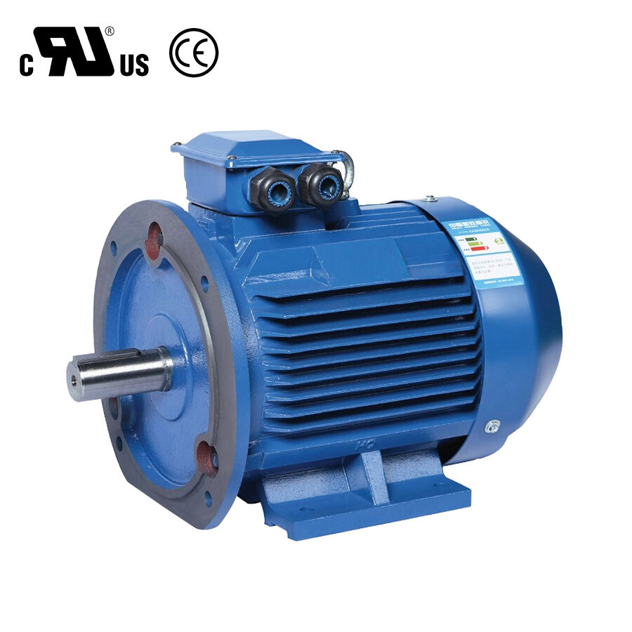
Run the Textile Machinery PM Motor uncoupled at low speed (100 RPM) to confirm correct rotational direction. Gradually ramp rotational speed to maximum operating frequency, monitoring running current and mechanical vibration across all axes. Finally, couple the motor to the textile machine, calibrate current loop proportional-integral (PI) gains under full yarn package loads, and verify that thermal rise remains within specified design limits after four continuous hours of production.
To review technical drawings and textile drive specifications, visit the ENNENG Products Catalog and review solutions via ENNENG Textile Drive Engineering.
For technical support regarding textile motor commissioning protocols or drive parameter tuning, contact ENNENG:
Q: Why is magnetic pole angle identification essential when commissioning a Textile Machinery PM Motor?
A: Variable frequency drives utilize field-oriented vector control to apply current exactly 90 electrical degrees relative to the rotor magnetic field. If the encoder or resolver zero-position offset is misaligned, the drive injects current off-axis, producing high current draw, severe torque ripple, and motor overheating. Accurate pole angle calibration guarantees maximum torque per ampere and smooth yarn delivery.
Q: How do technicians prevent combustible fly lint from accumulating on textile motors?
A: Specialized textile motors utilize smooth, totally enclosed non-ventilated (TENV) or smooth-casing fan-cooled (TEFC) designs without external cooling fins where lint can catch. Routine maintenance protocols during commissioning should schedule periodic cleaning using dry compressed air and confirm that motor surface temperatures remain well below dust ignition thresholds per NFPA 654 rules.
Q: What causes sudden overcurrent trips during textile machine ramping?
A: Sudden overcurrent trips during speed ramp-up usually stem from poorly tuned inverter acceleration profiles or incorrect inertia ratio settings. If the drive acceleration rate exceeds the mechanical capability of loaded spinning packages, the motor draws peak saturation currents. Extending acceleration ramp times by several seconds or increasing speed controller integral gain resolves the issue.


 EN