
 EN

A Textile Machinery PM Motor can look healthy during a no-load handover and still create yarn breaks, uneven tension, abnormal noise, or nuisance drive trips once the line is running. That is why commissioning should not end when the shaft turns. For a permanent-magnet drive, the motor, VFD, feedback system, machine mechanics, and process load must agree with one another.
This field checklist is written for maintenance teams diagnosing a newly installed Textile Machinery PM Motor. Start with safety, capture a baseline, and change one variable at a time. If the machine must run with guards removed or terminals exposed, stop and use the site’s lockout, electrical-safety, and machine-safety procedure instead of attempting a live adjustment.
First, establish a safe and useful fault baseline
Before changing a parameter, record the fault code, operating speed, commanded speed, current, DC-bus condition, ambient temperature, and what the textile machine was doing when the symptom appeared. Was it accelerating a roller, holding a winding tension, creeping for threading, or running production speed? A Textile Machinery PM Motor fault that occurs only during acceleration has a different starting point from one that appears after thirty minutes at steady speed.
- Confirm isolation, guarding, emergency-stop operation, and grounding according to the site procedure.
- Compare the motor nameplate, drive nameplate, wiring drawing, and commissioning record before editing settings.
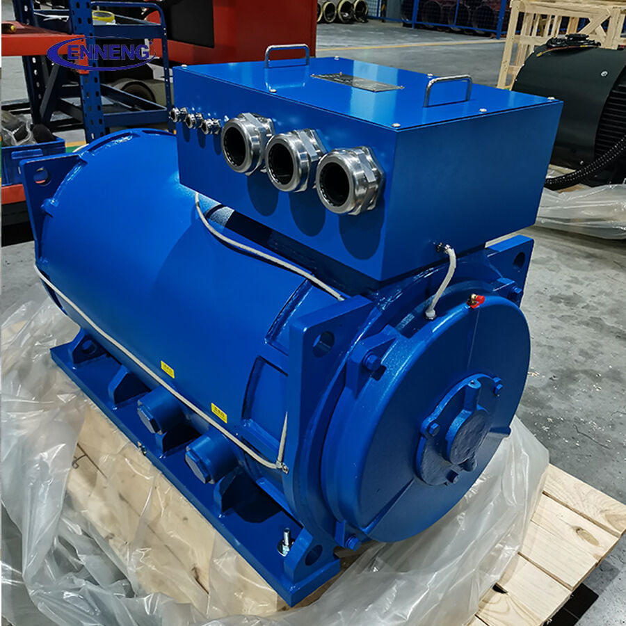
- Inspect the terminal box for loose lugs, damaged insulation, moisture, lint buildup, and incorrect cable screening termination.
- Photograph the original VFD parameter set and preserve alarms or trend data.
Insulation-condition testing and electrical measurements should follow the motor and drive manufacturer’s instructions. IEC 60034-1 provides general rating-and-performance context for rotating machines, but it does not replace the limits and test method approved for the particular motor, cable, and VFD installation.
1. Do not skip mechanical mounting, alignment, and the driven load
Field vibration is often blamed on the Textile Machinery PM Motor, but a flexible base, a misaligned coupling, an overtight belt, or a resonant guard can be the real source. Check the mounting bolts, feet, shims, coupling alignment, pulley runout, belt tension, and clearance around the fan and shaft. Keep the alignment record with the commissioning file; established motor-commissioning practice treats mechanical alignment as a documented verification, not a visual guess.
Then rotate the machine safely by hand where permitted. Binding rollers, seized bearings, accumulated fiber, or an unexpectedly high breakaway torque can make a correctly wired PM Synchronous Motor look like it has a control problem. The same applies to textile sections with rapidly changing inertia: a winding roll near full diameter may demand very different acceleration torque from an empty core.
2. Verify power cable, protective earth, and phase sequence against the drive design
Do not assume that a cable label reflects the final connection. Confirm conductor identification, torque the terminals to the specified value, verify protective-earth continuity, and inspect shielding and separation from sensitive feedback wiring. In a Textile Machinery PM Motor installation, poor shielding or a damaged encoder cable may show up as unstable speed long before it causes a clear communication alarm.
For a PM Synchronous Motor, phase order and rotor-position information must match the VFD’s control method. Do not swap motor leads to “see what happens” while encoder or resolver feedback is connected. Use the manufacturer’s commissioning sequence, and de-energize before changing field wiring. Incorrect phase/feedback relationships can produce reverse motion, rough starting, overcurrent, or an immediate trip.
3. Treat VFD motor data as a commissioning item, not a copy-and-paste field
A Textile Machinery PM Motor needs the correct motor model or rated data in the drive: rated voltage, current, power, frequency or base speed, pole or encoder information, and control mode. If the VFD supports a motor identification or auto-tune routine, run only the version approved for the coupled machine. A rotating tune can move the driven equipment and may be unsuitable until the mechanical system is ready.
Check current limits, acceleration/deceleration ramps, torque limits, carrier-frequency settings, and braking or regeneration settings against the actual production cycle. A drive that trips only while decelerating a high-inertia roller may be exposing a DC-bus or braking-path issue, not a defective Textile Machinery PM Motor. Likewise, a very aggressive speed loop may create hunting that operators describe as “surging.”
4. Check feedback, references, and synchronization before chasing motor faults
Textile processes depend on speed relationships. Review encoder polarity, pulse count or resolver setup, zero-position references where applicable, speed-reference scaling, and master/follower ratios. If several axes share a line reference, compare commanded and actual speeds during a controlled low-speed test. A Textile Machinery PM Motor that follows a bad reference faithfully cannot correct the process by itself.
Look for intermittent feedback connections at bend points, connector backshells, and cable routes near power conductors. When speed ripple follows a specific machine position, inspect the mechanical transmission too. When it follows electrical noise, encoder signal quality and grounding become more likely suspects.
5. Check thermal conditions, dust, and cooling paths under real duty
Textile rooms can add lint, humidity, and elevated ambient temperature to a continuous-duty application. Inspect air passages, fins, fan operation, terminal-box seals, and the enclosure condition before treating high temperature as an internal motor failure. If the installation uses a higher ingress-protection enclosure, remember that environmental protection and heat dissipation must be considered together.
Measure and trend temperature only with approved methods and compare it with the motor’s documented limits. A Textile Machinery PM Motor may run acceptably during a brief unloaded test but overheat when lint restricts cooling and the line operates at its actual tension and speed. Check the duty cycle, load current, ventilation, and ambient temperature together rather than selecting one reading as the answer.
6. Use a controlled test sequence instead of random adjustments
- Run uncoupled only if the manufacturer and machine procedure permit it; record vibration, direction, feedback stability, and no-load current.
- Run at low speed with the load connected; check for rubbing, belt tracking, backlash, and stable feedback.
- Increase speed in defined steps while logging current, vibration, temperature, and drive alarms.
- Test acceleration, deceleration, and the specific process mode that triggered the complaint.
- After each change, document the setting, result, and whether the symptom changed.
The goal is not to make the fault disappear temporarily. The goal is to identify whether the Textile Machinery PM Motor, the VFD setup, the feedback circuit, the installation, or the driven textile mechanism is responsible.
The ENNENG Customisation Advantage
No two industrial facilities share the same spatial or mechanical constraints. ENNENG stands out because we do not just supply off-the-shelf catalogue products; we specialise in delivering a tailor-made permanent magnet motor tailored to your specific application .
Supported by our elite R&D team consisting of engineers from the National Rare Earth Permanent Magnet Engineering Centre, and backed by dozens of patents, we customise high-voltage (6kV/10kV) and low-voltage (380V/660V/1140V) solutions to match your existing footprint. From water treatment facilities and oil wells to explosion-proof mining environments, we deliver optimal performance where general-purpose motors fail .
If you are evaluating commercial permanent magnet motors for sale and need an engineered drive solution that guarantees efficiency and longevity, ENNENG is your trusted partner.Contact ENNENG Today.Speak to our technical engineering team to receive a customised drive proposal.
- WhatsApp: +86 18562780228
- E-Mail: [email protected]
- Phone: +86 532 66000559
When to pause and involve the supplier or drive specialist
Stop field debugging and escalate when there is insulation damage, repeated overcurrent at a verified safe load, unusual bearing noise, evidence of rotor contact, persistent encoder/drive mismatch, or a requirement to alter protected drive parameters without approved values. Share the nameplate data, drive backup, wiring diagram, fault history, measured conditions, and commissioning record. Clear evidence shortens remote support and avoids repeated component swaps.
For a new Textile Machinery PM Motor, the most useful handover is not simply “runs normally.” It is a documented baseline showing alignment, wiring verification, VFD parameters, feedback status, temperature behavior, and production-mode observations. That record makes the next fault easier to isolate and gives the process team a reliable starting point.

