
 EN

A Permanent Magnet Motor PMSM can deliver compact torque, high efficiency, and precise speed control, but the rotor magnets are not immune to the operating environment. Demagnetization becomes a serious concern when heat, an opposing magnetic field, or mechanical damage pushes a magnet beyond its safe operating point. The important distinction is between a temporary reduction in magnetic flux at elevated temperature and irreversible loss of magnetization after the machine cools.
For maintenance teams, the practical question is not whether a motor is running; it is whether its thermal, electrical, and mechanical margins remain intact during the worst parts of its duty cycle. A well-matched PM Synchronous Motor can operate reliably for a long time, while the same design may face accelerated risk if a changed load, VFD setting, cooling path, or winding fault is left unchecked.
Why demagnetization changes motor behavior
Rotor magnets establish the air-gap flux that allows a Permanent Magnet Motor PMSM to produce torque. If that flux weakens, the drive may command more current to maintain the required speed or torque. That extra current adds stator loss and heat, which can further increase stress. This feedback pattern is why a small loss of magnetic margin should be investigated rather than treated as an isolated performance issue.
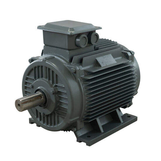
In industrial service, early symptoms can include reduced torque reserve, unexpected current demand at a familiar load, higher winding temperature, vibration changes, or a control system that reaches its current limit more often. None of these symptoms proves demagnetization by itself. They are signals to compare operating data with a known healthy baseline and to rule out load, bearing, cooling, inverter, and sensor problems.
1. Excessive magnet temperature
Temperature is the most common starting point for demagnetization risk. As rotor temperature rises, a magnet’s available coercivity falls. At a sufficiently unfavorable operating point, the opposing field inside the motor can produce permanent flux loss. The exact temperature margin depends on the magnet grade, rotor geometry, duty cycle, cooling design, and magnetic circuit; a nameplate motor temperature alone is not a substitute for rotor thermal analysis.
Common contributors are blocked airflow, a contaminated heat exchanger, elevated ambient temperature, poor cabinet ventilation, repeated overloads, and a process that now runs at higher speed or torque than it did at commissioning. High-frequency operation can also increase loss and temperature rise. In other words, a Permanent Magnet Motor PMSM may be thermally acceptable at one operating point yet have little margin during high-speed, high-torque, or repeated transient operation.
A cooling problem is easy to label as a stator issue only. In practice, that diagnosis is incomplete. Rotor heat can be difficult to observe directly, especially in enclosed equipment. Trend the available temperatures, verify the cooling medium and flow path, and use the machine supplier’s limits for the actual magnet grade and rotor construction.
2. Aggressive flux weakening or incorrect d-axis current control
In vector-controlled drives, negative d-axis current is used for flux weakening when speed must extend beyond the base-speed region. Used within the motor and drive design envelope, this is a normal control method. The risk rises when the negative d-axis current is excessive, poorly limited, applied at high temperature, or combined with a magnetic design that has little demagnetization margin.
For a PM Synchronous Motor, commissioning should confirm current limits, motor parameter values, encoder or resolver polarity, and the flux-weakening schedule. Incorrect motor data or a tuning change can make the drive apply a field condition different from what the designer intended. Review fault logs and trend d-axis current during acceleration, overspeed events, field-weakening operation, and recovery from a process upset. Do not assume that a generic VFD template protects every Permanent Magnet Motor PMSM.
3. Short circuits, overcurrent, and abnormal transients
Electrical faults can combine local heating with a strong opposing field. Inter-turn shorts are especially important because high current can circulate in a small section of winding, creating a concentrated hot spot. Phase-to-phase faults, inverter faults, poorly coordinated protection, and repeated stalled-rotor events can also drive currents far beyond normal thermal conditions.
The condition is not limited to a dramatic trip. Recurrent nuisance trips, unexplained current imbalance, deteriorating insulation measurements, or a rising current requirement at constant load deserve engineering review. Capture event waveforms where the drive can provide them. Then inspect the system-level cause: cable condition, motor terminal integrity, drive protection settings, supply quality, and whether the driven equipment is forcing overload or repeated rapid reversals.
4. Mechanical damage, vibration, and rotor integrity problems
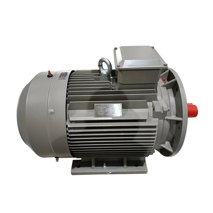
Demagnetization is usually discussed as a thermal or electromagnetic problem, but mechanical faults can remove the margin that keeps those mechanisms under control. Bearing deterioration, rotor rub, poor alignment, imbalance, or damage caused by shock can increase vibration and heat. They may also damage magnet retention or alter the air gap. Once the rotor geometry changes, local magnetic loading and local heating can become less predictable.
A useful maintenance habit is to investigate the sequence, not just the alarm. Did vibration rise before temperature? Did a bearing replacement change the alignment? Did the current signature change after a process jam? This chronology can distinguish a root cause from the later symptom that appears on a drive display.
5. Aging, contamination, and unsuitable duty changes
Time alone does not guarantee magnet failure, but long exposure to heat, corrosive contaminants, moisture ingress, or repeated severe thermal cycling can reduce reliability. A Permanent Magnet Motor PMSM installed in a harsher location than originally specified needs a new assessment of sealing, cooling, insulation health, and duty cycle. The same applies when production adds longer high-load runs, more start-stop cycles, or a hotter ambient season.
Keep configuration control around both motor and drive. A replacement motor with a different magnet grade, a revised VFD firmware setting, or a change to encoder feedback can alter the real operating margin. Specification matching should include the full motor-drive-load system, not rated power alone.
A practical decision point for industrial teams
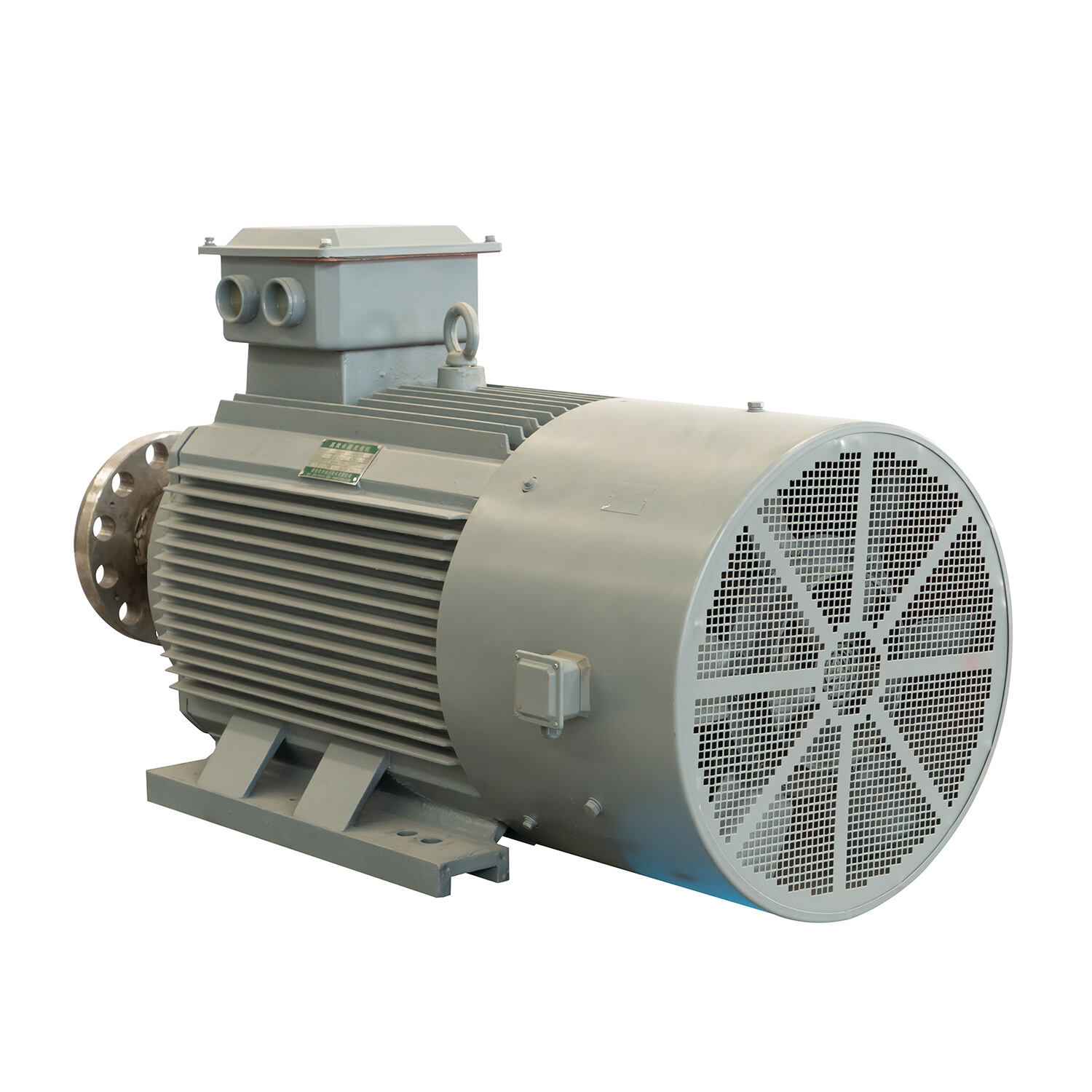
Demagnetization risk rarely comes from one number on a dashboard. It emerges when a Permanent Magnet Motor PMSM faces a combination of high rotor temperature, an adverse control field, fault current, and reduced cooling or mechanical integrity. Treat the manufacturer’s magnet and drive limits as the governing design data, then validate them against the actual duty cycle.
For new equipment, involve the motor supplier early when the application needs high ambient operation, frequent overloads, sustained flux weakening, severe contamination exposure, or rapid reversals. For installed equipment, use trends and fault history to identify lost margin before reduced torque becomes a production interruption. That approach gives a PM Synchronous Motor the operating conditions it was designed to handle without making claims that any machine can tolerate every industrial upset.
If you are evaluating commercial permanent magnet motors for sale and need an engineered drive solution that guarantees efficiency and longevity, ENNENG is your trusted partner.Contact ENNENG Today.Speak to our technical engineering team to receive a customised drive proposal.
- WhatsApp: +86 18562780228
- E-Mail: [email protected]
- Phone: +86 532 66000559

