
what-mechanical-matching-obstacles-may-occur-during-retrofit-induction-to-pmsm-field-execution, what-mechanical-matching-obstacles-may-occur-during-retrofit-induction-to-pmsm-field-execution, /blog
EN

2026/09/15
The hardest part of swapping an old induction machine for a permanent magnet unit is rarely the electrical spec; it is the physical fit on a crowded, aging frame. A Retrofit Induction to PMSM must land on the same foot, share the shaft height, and turn the same load without reshaping the foundation. Field execution exposes mismatches that drawings smooth over, and a half-inch difference in shaft centerline can stall the whole job on the floor.
One bulk-conveyor line planned a Retrofit Induction to PMSM on a drive that had run for twenty years. The new unit arrived with a different shaft height and a shorter body, so the coupling would not reach and the foot holes missed the base. The team fabricated spacers and re-drilled the bedplate on site, losing a shift and risking alignment. The Retrofit Induction to PMSM delivered its saving only after the mechanical fit was forced right, because no one had measured the old centerline before the order was placed.
Aged machines were built to older frame standards, and the surrounding base, coupling, and driven load were tuned to that exact geometry. A Retrofit Induction to PMSM built to a newer frame can sit higher or longer than the unit it replaces, so the shaft no longer lines up with the load. Paint buildup, worn feet, and distorted beds add millimeters that compound. The Retrofit Induction to PMSM therefore meets the building's physical history, and the obstacle is the gap between the catalog and the real, settled frame.
The obstacles cluster around geometry and dynamics: shaft height and foot pattern, then inertia and coupling behavior. A Retrofit Induction to PMSM plan that measures both before ordering avoids the on-floor fabrication that costs time and alignment.
Shaft centerline height decides whether the coupling lines up, and foot hole pattern decides whether the unit bolts down without drilling. A Retrofit Induction to PMSM with a different centerline forces shims or a new bedplate, each a chance to introduce misalignment. Foot patterns vary across frame generations, so the bolt holes may not match the old base at all. Measuring the existing centerline and hole layout before the Retrofit Induction to PMSM is ordered turns a field crisis into a checked box on the quote.
The permanent magnet rotor has its own inertia and a different starting behavior than the induction unit it replaces, and the existing coupling may not suit it. A Retrofit Induction to PMSM that changes reflected inertia can stress the coupling or shift the resonance of the train. A rigid coupling that worked on the old machine may transmit shock the new rotor does not want. Matching the coupling and checking the inertia ratio keeps the Retrofit Induction to PMSM stable, because the mechanical interface, not the nameplate, governs the first spin.
Mounting and balance standards turn the fit into measurable checks. A Retrofit Induction to PMSM aligned to them runs true and stays available, which is why the standard should lead the field plan.
IEC 60034-7 defines mounting arrangements and frame dimensions, the reference for whether a Retrofit Induction to PMSM will bolt to the old base and share the shaft height. Checking the standard before order prevents the on-site drilling and shimming that cost the conveyor line a shift. The standard gives the foot and centerline data the field needs, so the Retrofit Induction to PMSM is matched on paper first and on the floor second, with no surprises in between.
ISO 1940-1 sets balance grades so the new rotor runs true after the mechanical fit, and ISO 10816 gives vibration limits to confirm the alignment held. A Retrofit Induction to PMSM that passes both proves the field execution was clean, because a good balance and a low vibration trend mean the shaft lines up with the load. These standards turn the mechanical match from a guess into a measured result the site can log and trust over time.
Choosing and fitting the unit means measuring the old machine as carefully as specifying the new one. A Retrofit Induction to PMSM performs to its rating only when the mechanical execution matches the real frame, not the ideal drawing.
Measure shaft centerline height, foot hole pattern, body length, and coupling type on the running machine before quoting. A Retrofit Induction to PMSM should match those numbers or arrive with a documented adapter plan, not a hope. Confirm the inertia ratio with the driven load and pick a coupling suited to the new rotor. When the Retrofit Induction to PMSM is specified against the measured frame, the field execution becomes a bolt-up instead of a fabrication job on the floor.
Install against a written fit plan: verify centerline with shims if needed, torque the feet to spec, and align the coupling before the first run. A Retrofit Induction to PMSM should get a vibration reading after alignment and a follow-up after the first loaded week, because small fit errors show under real torque. Keep the measured frame data with the new record, and inspect the coupling and feet on the planned route, so the mechanical match stays true through the operating life.
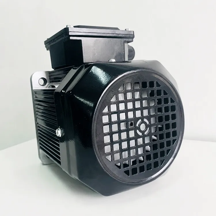
Old machines follow older frame standards, and the base, coupling, and load were tuned to that exact geometry. A Retrofit Induction to PMSM built to a newer frame may sit higher or longer, so the shaft no longer lines up and the feet miss the holes. Paint, worn feet, and distorted beds add millimeters that compound. The obstacle is the gap between the catalog drawing and the real, settled frame on the floor.
Shaft centerline height and foot hole pattern lead. A Retrofit Induction to PMSM with a different centerline forces shims or a new bedplate, and foot patterns vary across frame generations, so bolts may not line up. Either one turns a bolt-up into fabrication. Measuring the existing centerline and holes before order prevents the on-site drilling that cost the conveyor line a lost shift and a risky alignment.
Yes, because the permanent magnet rotor has its own inertia and a different start behavior than the induction unit it replaces. A Retrofit Induction to PMSM that changes reflected inertia can stress the coupling or shift the train resonance. A rigid coupling that suited the old machine may transmit shock the new rotor does not want. Matching the coupling and checking the inertia ratio keeps the first spin stable and safe.
IEC 60034-7 defines mounting arrangements and frame dimensions, the reference for whether the new unit bolts down and shares the shaft height. Checking it before order prevents field drilling and shimming. ISO 1940-1 sets balance grades and ISO 10816 gives vibration limits to confirm the alignment held, so the Retrofit Induction to PMSM is matched on paper first and proven true by measurement after the fit.
Adapters and shims can close a centerline or hole gap, but they add alignment risk and fabrication time on the floor. A Retrofit Induction to PMSM should arrive with a documented adapter plan when the frame differs, not a hope that the fit works out. Used carefully, adapters recover the job; used blindly, they introduce misalignment that the vibration trend will later expose as a bearing or coupling fault.
Install against a written fit plan: shim to centerline, torque the feet, and align the coupling before run. A Retrofit Induction to PMSM deserves a vibration reading after alignment and a follow-up after the first loaded week, because small fit errors surface under real torque. Keep the measured frame data with the new record and inspect the coupling and feet on the route, so the mechanical match stays true through the operating life.


 EN