
 EN

What on-site power-supply matching problems may affect operating effects of Retrofit Induction to PMSM projects
In a Retrofit Induction to PMSM project, selecting a motor with the right rated power is necessary, but it is not the same as making the installation work well. The replacement motor, inverter, incoming supply, protection devices, cable route, grounding arrangement, and driven load form one electrical system. If those pieces are not matched, a Retrofit Induction to PMSM installation can show nuisance trips, unstable speed, abnormal heating, or disappointing energy results even when the mechanical installation looks sound.
From an application-engineering viewpoint, the useful question is not simply “is the supply voltage correct?” It is: can the site deliver a stable, compatible supply to the drive, and can the drive deliver a compatible waveform to the motor across the real duty cycle? That distinction helps teams investigate a Retrofit Induction to PMSM project before commissioning turns into repeated trial and error.
Why nameplate matching is not enough
An induction motor connected directly to a fixed-frequency supply and a PMSM operated through a variable-frequency drive do not place identical demands on a site. A Retrofit Induction to PMSM design commonly introduces a drive front end, DC bus, switching output, control feedback, and new protection settings. The nominal kW, voltage, and frequency on the old motor nameplate are useful starting points, not a complete acceptance test.
A Permanent Magnet Motor PMSM system may offer useful efficiency and controllability in the right application, particularly where the load varies. Still, a performance estimate measured at a defined operating point should not be treated as a site guarantee. Ambient temperature, load profile, cable length, supply quality, and control tuning all influence the operating result.
1. Incoming voltage may be nominal but still unsuitable
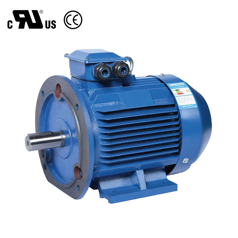
The first Retrofit Induction to PMSM issue is often voltage variation at the drive terminals rather than at the main switchboard. Long feeders, undersized conductors, weak transformers, shared high-current loads, or loose connections can create a voltage drop when the equipment accelerates or when another process starts. The drive may then report undervoltage, limit torque, or trip to protect its DC bus.
For a Retrofit Induction to PMSM assessment, record voltage at the point of common coupling and at the drive input during normal running, acceleration, and likely worst-case simultaneous loads. Check the motor-and-drive documentation for the allowed combined voltage and frequency operating envelope. Do not substitute a generic tolerance for the supplier’s documented limits.
2. Phase imbalance can raise current and thermal stress
Unequal phase voltages can produce unequal input current and additional heating. Power-quality guidance consistently treats voltage unbalance as a condition that deserves investigation because it can increase losses and stress electrical equipment. In a Retrofit Induction to PMSM project, the inverter may regulate motor current, but that does not make a poor incoming three-phase supply harmless to the rectifier, DC bus, or upstream components.
Measure all three line-to-line voltages and phase currents under load. Compare the results with the drive manufacturer’s limits, then inspect upstream fuses, contactors, terminals, transformer taps, and shared loads. Correct the site cause before compensating with aggressive software settings in a Retrofit Induction to PMSM drive.
3. Harmonics and distorted supply can complicate the retrofit
A drive-based Retrofit Induction to PMSM installation both responds to and may contribute to harmonic conditions. Existing non-linear loads, capacitor banks, generators, or multiple drives can make the input waveform less clean. Symptoms can include unexplained protective-device operation, transformer heating, interference with controls, or unstable DC-bus behavior. The exact risk depends on the drive topology, source impedance, cable system, and the rest of the plant.
Start with a power-quality survey where the symptoms occur. Review total harmonic distortion, individual harmonic components where available, and any resonance risk involving correction capacitors. A line reactor, DC choke, active or passive filtering, or a revised capacitor-bank arrangement may be appropriate only after the measurement and the drive supplier’s guidance support it. Adding parts without diagnosing the electrical system can move the problem rather than remove it.
4. Frequency, control mode, and speed references may conflict
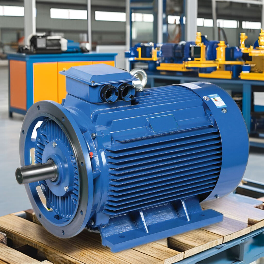
A Retrofit Induction to PMSM project normally shifts speed control from slip-dependent induction-motor behavior to a closed-loop PMSM control strategy. The drive must receive the correct motor data, feedback configuration, and speed reference. A legacy analogue signal, PLC scaling rule, or process interlock that worked with the old motor may command an unintended speed or ramp after the conversion.
Verify rated speed, pole-pair-related parameters, encoder or sensorless requirements, acceleration and deceleration ramps, minimum speed, maximum speed, and direction logic. Confirm that the reference signal is isolated and scaled as intended. If an application needs torque control or fast response, validate that requirement under a guarded site test rather than assuming a default vector-control setup is adequate for every Retrofit Induction to PMSM application.
5. Cable and output-waveform matching are often overlooked
The inverter output in a Retrofit Induction to PMSM system is a pulse-width-modulated waveform, not the same waveform supplied directly by the utility. Long motor cables can increase reflected-wave stress, common-mode current, bearing-current risk, and electromagnetic interference. Cable shield termination, earthing continuity, routing near signal wiring, and the selected output filter all deserve review.
Use the drive documentation to define acceptable cable length, cable type, grounding practice, and any dV/dt or sine-wave-filter requirement. A good Retrofit Induction to PMSM commissioning record identifies the actual installed cable length and termination method instead of assuming that the original induction-motor feeder is automatically suitable.
6. Protection coordination may no longer match the equipment
Upstream breakers, fuses, overload relays, contactors, thermal sensors, and emergency-stop logic should be reviewed as a system. A Retrofit Induction to PMSM drive has its own protective functions, but those functions must coordinate with the site’s electrical protection and process safety arrangements. An induction-motor overload relay left in an unsuitable location, for example, can produce avoidable trips or fail to provide the intended protection.
Confirm the drive input protection, short-circuit rating, residual-current-device compatibility where applicable, braking arrangement, motor thermal model, and safe stop architecture against the documented design. Qualified electrical personnel should validate changes to protective devices and safety circuits.
A practical power-supply checklist for Retrofit Induction to PMSM work
- Document supply voltage, frequency, source capacity, and available fault information at the installation point.
- Measure voltage drop, phase balance, current, and power quality during realistic load events.
- Check that the drive input rating, motor voltage class, and control supply are compatible with the site system.
- Review cable length, shielding, grounding, routing, and output-filter requirements.
- Validate acceleration, deceleration, regenerative energy handling, and upstream protection coordination.
- Commission the Retrofit Induction to PMSM system at representative loads while recording alarms, temperatures, current, and speed behavior.
Contact US
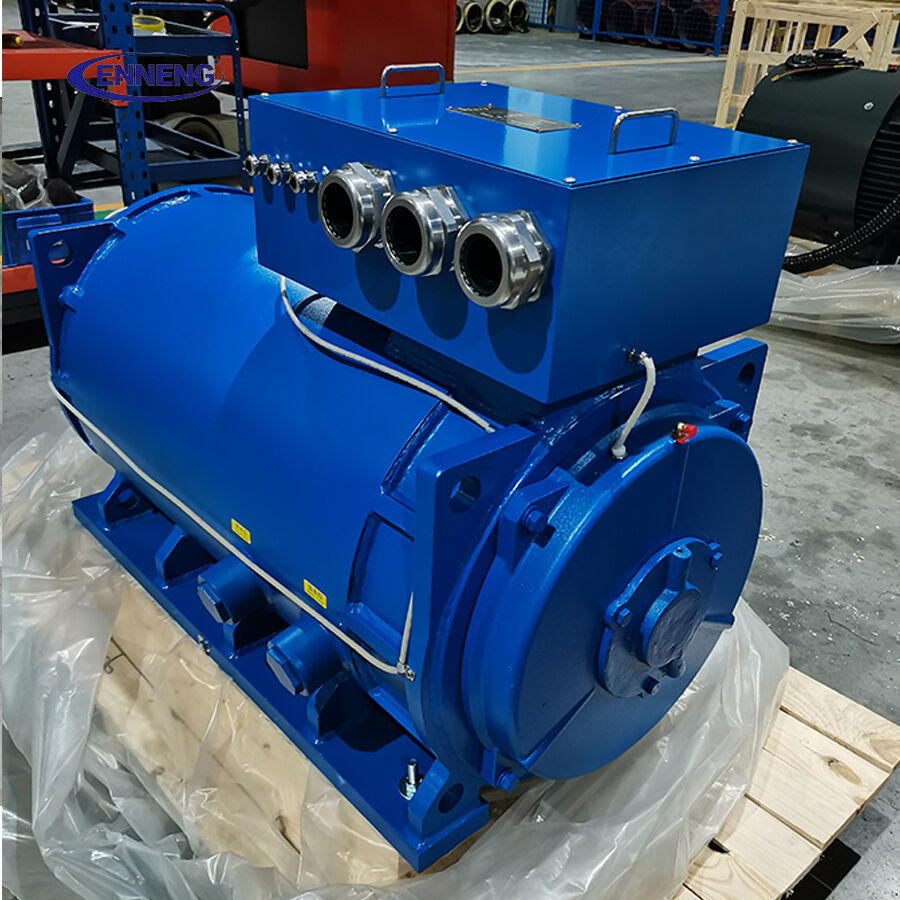
If you are evaluating commercial permanent magnet motors for sale and need an engineered drive solution that guarantees efficiency and longevity, ENNENG is your trusted partner.Contact ENNENG Today.Speak to our technical engineering team to receive a customised drive proposal.
- WhatsApp: +86 18562780228
- E-Mail: [email protected]
- Phone: +86 532 66000559
What good commissioning looks like
A disciplined Retrofit Induction to PMSM commissioning plan establishes a baseline before the old equipment is removed, then checks electrical behavior after the new drive and motor are installed. It separates a mechanical load problem from a supply problem and a control problem. That saves time because it prevents a team from changing motor parameters to mask an upstream voltage or cable issue.
A successful outcome is not simply that the Retrofit Induction to PMSM installation starts and turns. It is that it reaches the required process speed and torque without repeated trips, unexplained heating, or unacceptable disturbance to the rest of the site. Treat the power supply as part of the retrofit scope from design through handover, and the operating effect will be far more predictable.

