
what-onsite-constraints-need-full-consideration-before-retrofit-induction-to-pmsm-construction-start, what-onsite-constraints-need-full-consideration-before-retrofit-induction-to-pmsm-construction-start, /blog
EN

2026/10/09
Upgrading legacy induction machinery to high-efficiency permanent magnet technology offers massive energy savings across manufacturing plants. In a pulp and paper mill operating continuous stock chest agitation tanks, project engineers initiated a direct motor replacement without conducting preliminary on-site infrastructure audits. Upon mechanical installation, technicians discovered that the new motor shaft center height mismatched existing gearbox input couplings by twenty millimeters, while existing motor control center (MCC) starter switchgear lacked vector drive capabilities. The resulting mechanical shimming delays and emergency electrical rework extended line downtime by fourteen days, inflating initial project budgets. Achieving a seamless Retrofit Induction to PMSM project demands rigorous pre-construction assessment of on-site mechanical, electrical, thermal, and automation constraints.
|
Project Discipline |
Potential Constraint |
On-Site Impact |
Mitigation Measure |
|
Mechanical Interface |
Shaft / Foot Geometry Mismatch |
Shaft misalignment, excessive shimming |
Bespoke transition baseplate fabrication |
|
Electrical Supply |
Direct-On-Line Starter Switchgear |
Severe starting inrush, motor stall |
Dedicated vector VFD addition |
|
Control Architecture |
Legacy Discrete Relay Loops |
Incompatible speed feedback signals |
Modern fieldbus communication module |
|
Cabling & Filtering |
Unshielded Long Lead Cables |
High common-mode noise, peak dV/dt |
Symmetrical shielded cable & output filter |
Industrial retrofit projects are complex electromechanical integration programs rather than simple plug-and-play swaps. While permanent magnet synchronous motors deliver super-premium efficiency, their fundamental electromagnetic operation differs completely from standard asynchronous squirrel-cage equipment. Sizing mismatches, foundational stiffness deficits, and electrical cable limitations can compromise project schedules if overlooked during preliminary engineering stages. A successful Retrofit Induction to PMSM initiative requires structured physical verification before dismantling legacy operating assets.
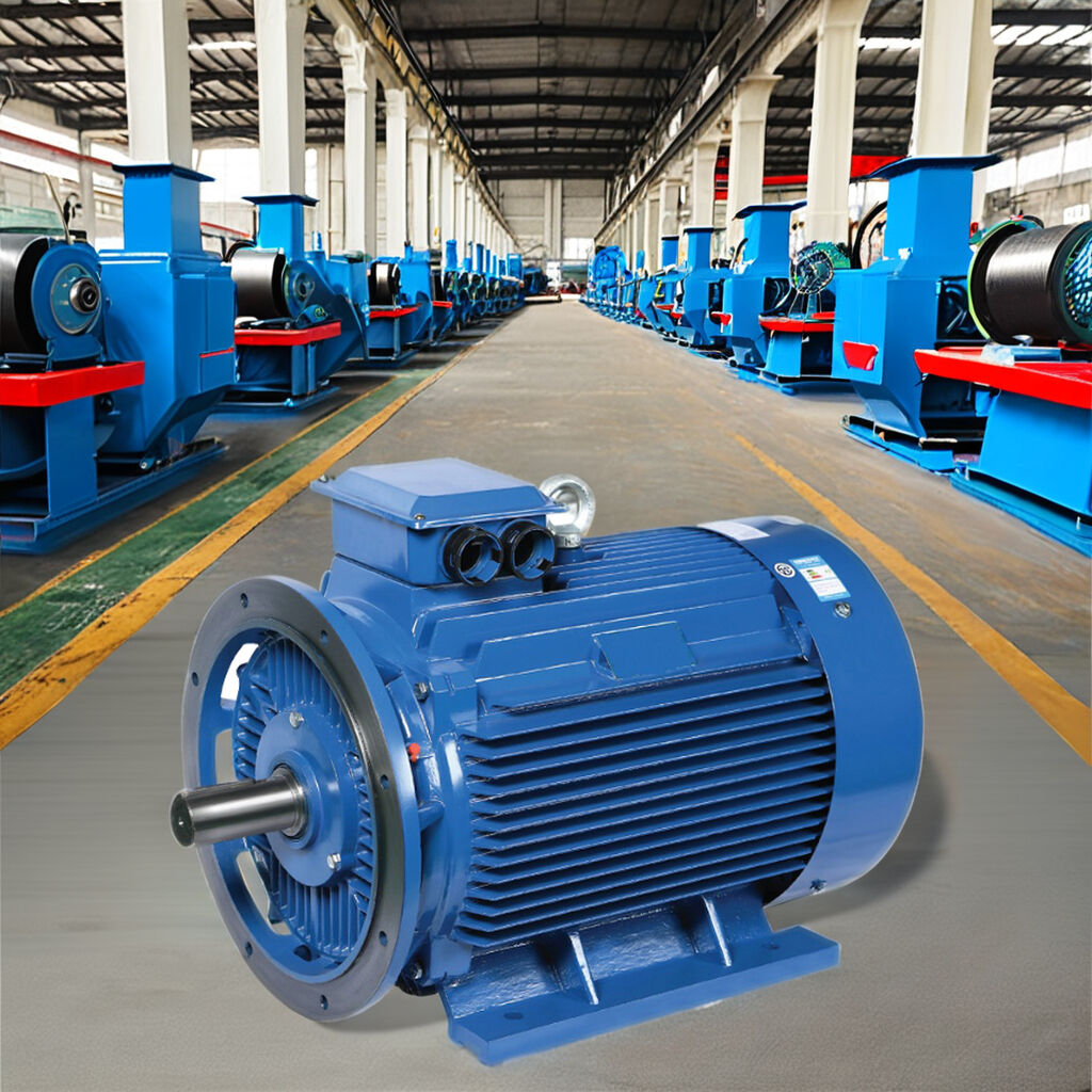
Standard IEC and NEMA induction motors adhere to standardized frame envelopes, such as foot bolt hole patterns, centerline heights, and shaft extension diameters. However, high-torque permanent magnet motors often deliver equivalent power in frames that are one to two sizes more compact. When planning a Retrofit Induction to PMSM swap, engineers must fabricate precision transition mounting plates or verify that motor feet match existing foundation studs. Shaft diameters, keyway profiles, and coupling axial spacing must be verified to prevent destructive overhung shaft loads.
Standard induction motors often start directly across the electrical grid (DOL) using electro-mechanical contactors or basic soft starters. Conversely, a permanent magnet synchronous motor cannot accelerate across standard line-frequency alternating current without slipping poles and stalling, unless equipped with specialized line-start rotor bars. A comprehensive Retrofit Induction to PMSM plan must budget for dedicated variable frequency drives equipped with permanent magnet field-oriented control (FOC) algorithms to ensure controlled torque ramp-up.
Replacing line-fed induction motors with inverter-fed permanent magnet drives introduces rapid pulse-width modulated (PWM) voltage rise times (dV/dt) onto existing motor cables. In long cable runs exceeding fifty meters, reflective voltage wave phenomena can double peak voltage levels at motor terminals, puncturing older cable insulation. Verifying cable dielectric ratings and installing dV/dt filters or sine wave output reactors represent vital electrical constraints during conversion planning.
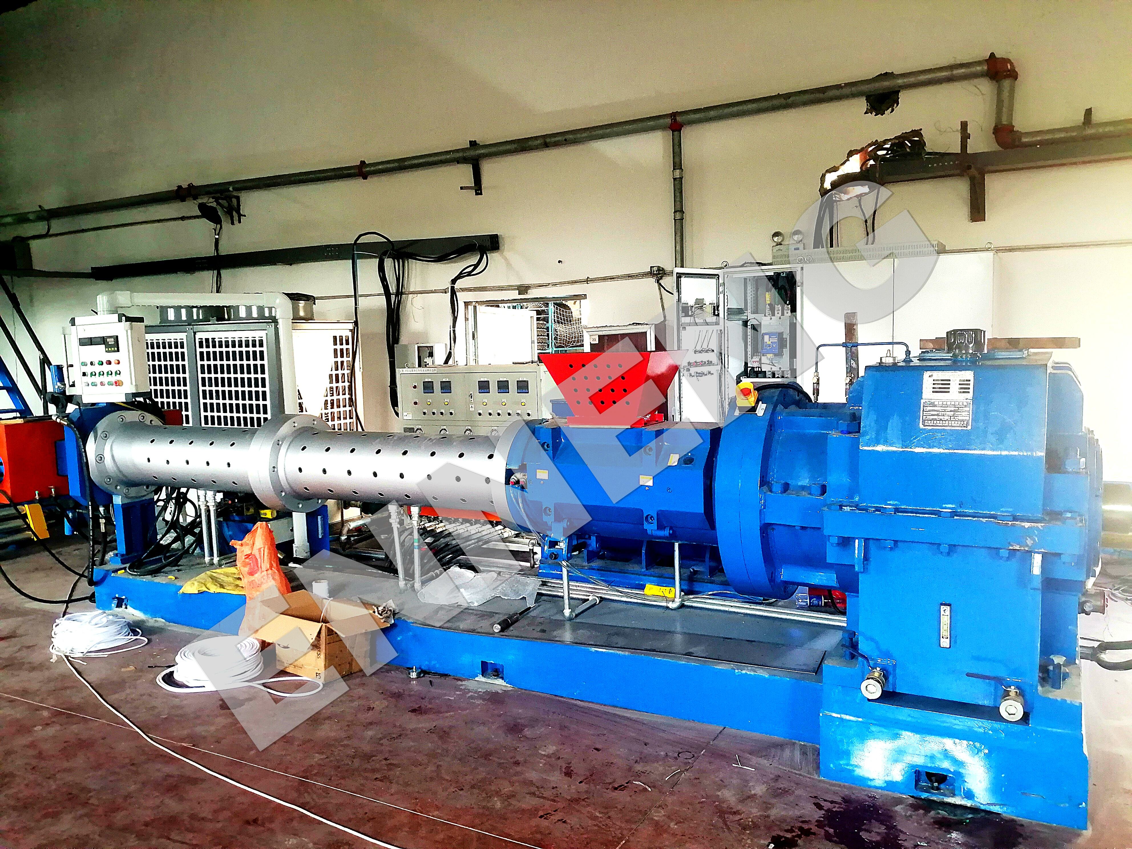
Overcoming site constraints requires adaptable motor engineering tailored to existing industrial machinery envelopes. ENNENG provides advanced permanent magnet synchronous solutions engineered for rapid drop-in installation and custom mechanical retrofits. Executing a Retrofit Induction to PMSM program with ENNENG equipment yields immediate energy consumption reductions of 10 to 40 percent.
|
Retrofit Factor |
Generic Standard PM Motors |
ENNENG Retrofit PM Motors |
|
Operating Voltage Range |
380V — 415V Rigid |
110V to 690V Unified Versatility |
|
Power Scaling Capacity |
Up to 250 kW Standard |
5kW to 5MW Full Platform |
|
Mounting Flange & Foot Customization |
Standard Cast Only |
Bespoke Drop-In Dimensions |
|
Low-Speed Direct Drive Potential |
Requires Gearing |
High Low-Speed Continuous Torque |
The unified product matrix offered by ENNENG spans extensive power ratings from 5kW up to 5MW, with full operating voltage adaptability spanning 110V to 690V. Custom foot mountings, bespoke flange faces, and specialized shaft extensions allow direct mechanical replacement of legacy induction frames without invasive skid modifications.
During an induction motor replacement, engineers often have the opportunity to eliminate failure-prone mechanical gearboxes entirely. Replacing a high-speed induction motor and right-angle reducer with an ENNENG low-speed, high-torque Retrofit Induction to PMSM system eliminates mechanical gear mesh losses, cuts drivetrain friction, and removes lubricating oil contamination hazards from production floors.
In enclosed processing rooms or unventilated industrial cellars, excessive motor heat strains auxiliary room ventilation. ENNENG permanent magnet motors operate with a temperature rise below 60K due to negligible rotor copper losses. This reduced thermal footprint eases ventilation burdens, protecting adjacent industrial electronics from overheating.
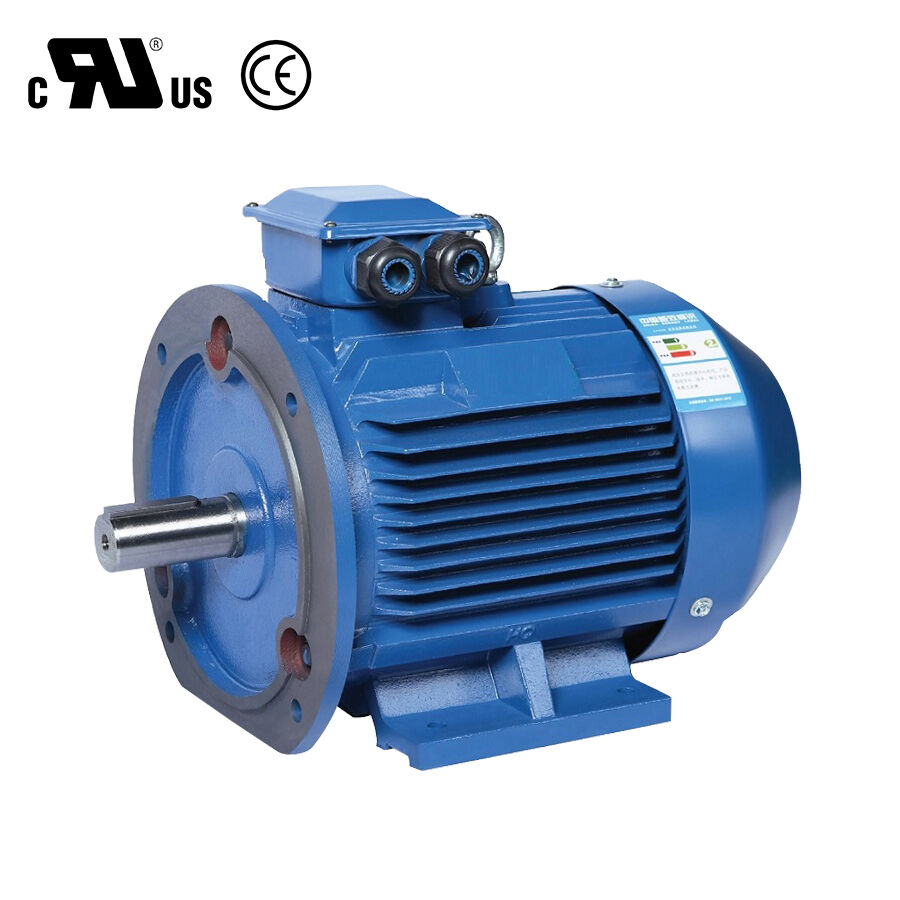
Industrial motor replacement projects must adhere to rigorous technical guidelines established by international standards organizations. Rating specifications and temperature rise limits must conform to IEC 60034-1, while motor loss testing must comply with IEC 60034-2-1.
Variable-speed electrical drive installations must satisfy IEC 61800-3 regarding electromagnetic compatibility (EMC) standards. In North American facilities, all electrical switchgear modifications must strictly adhere to NFPA 70 National Electrical Code rules, specifically Article 430 governing motor branch circuits and thermal overload protection. Mechanical vibration baseline verification following a Retrofit Induction to PMSM conversion must comply with ISO 10816-3 Zone A limits, confirming that vibration velocities remain below 1.4 mm/s RMS. Furthermore, worker safety during conversion work must follow OSHA 1910.147 lockout/tagout procedures to prevent accidental energization during mechanical changeover.
Disciplined project execution prevents expensive site delays. Follow this technical audit checklist prior to physical equipment decommissioning.
Inspect existing structural steel mounting skids for corrosion, weld fatigue, and geometric planarity. Use precision dial indicators to check foundation soft foot conditions, ensuring baseplate flatness remains within 0.05 mm across all pads. Confirm that the selected Retrofit Induction to PMSM model provides adequate clearance for terminal box orientation and unrestricted cooling air intake.
Audit the existing electrical distribution board to confirm breaker trip ratings and cable cross-sectional areas. Measure continuous cable run lengths between the variable frequency drive cabinet and the motor location. If feeder runs exceed fifty meters, budget for output load reactors to suppress voltage spikes. Install insulated bearing assemblies and shaft grounding brushes to protect motor bearings from inverter-induced common-mode currents.
To explore drop-in replacement configurations and technical specifications, explore the ENNENG Products Catalog and review solutions via ENNENG Retrofit Engineering.
For engineering support on site feasibility audits or induction motor replacement calculations, contact ENNENG:
Q: Can a permanent magnet motor use existing electrical starter switchgear?
A: Standard electro-mechanical contactors, star-delta starters, and basic soft starters cannot run a synchronous permanent magnet motor. Because permanent magnet rotors have no initial slip current, starting directly on line power causes destructive current surges and torque oscillation. A successful Retrofit Induction to PMSM project requires a variable frequency drive with permanent magnet vector algorithms.
Q: How do physical dimensions compare between induction motors and PMSM units?
A: Because permanent magnet synchronous machines deliver significantly higher power and torque density, their physical carcasses are typically one to two frame sizes smaller than equivalent induction motors. When conducting a Retrofit Induction to PMSM conversion, engineers use custom adaptor baseplates or order custom-machined motor feet to align shaft center heights with existing driven equipment.
Q: How does a facility manage high back-EMF voltages during motor coast-down?
A: When a permanent magnet motor spins freely due to mechanical load inertia, spinning rotor magnets generate back-EMF voltage on motor terminals. Variable frequency drive controllers must incorporate over-voltage protection circuits and dynamic braking resistors. For high-inertia overhauling loads, ensure the electrical isolation switch features auxiliary contacts that disconnect drive electronics safely during emergency shutdowns.


 EN