
 EN

Air Compressor PMSM Protection for Severe Impact Loads
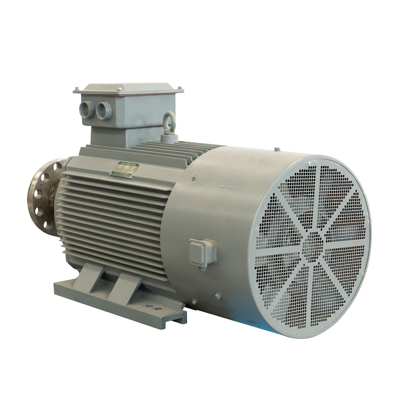
Automated glass container manufacturing plants operating heavy multi-stage reciprocating compressors 8,400 hours annually frequently encounter severe pressure pulsations and sharp torque spikes across every piston stroke. Operating an Air Compressor PMSM in these demanding conditions requires robust protection parameters to prevent sudden mechanical tripping, rotor overheating, and catastrophic stator insulation breakdown. Plant engineers modernizing compressor drives must establish comprehensive electrical, thermal, and sensor safeguards to ensure that every Air Compressor PMSM maintains dependable mechanical output across aggressive operating cycles.
Repetitive impact loading subjects the motor drive to severe electrical transients, rapid thermal accumulation, and acute mechanical vibration. Without targeted protection thresholds, high-frequency current pulses cause rapid magnet heating, elevate bearing mechanical fatigue, and create severe demagnetization risks that shorten machinery life. ENNENG develops advanced permanent magnet drive technologies engineered to eliminate impact-load vulnerabilities, providing verified electromagnetic resilience and continuous operational uptime across heavy industrial compression systems.
Dynamic Torque Spikes and Demagnetization Hazards in Compressor Duty
Reciprocating and rotary screw compressors introduce cyclic mechanical resistance that differs fundamentally from steady centrifugal pumping or fan ventilation. A reciprocating unit generates peak torque pulses reaching three to six times nominal rated torque during compression strokes. An Air Compressor PMSM lacks the natural slip of asynchronous induction machinery, meaning electromagnetic torque response occurs almost instantaneously. Consequently, severe current surges traverse stator windings and reach rotor magnets within milliseconds, demanding specialized system safeguards.
Cyclic Impact Loading and Rapid Stator Current Surges
During high-pressure compression cycles, the mechanical resistance encountered by an Air Compressor PMSM fluctuates rapidly within fractions of a second. When the compressor piston compresses process gas, the drive system experiences instantaneous load steps that force the inverter to supply massive torque-producing current. If an Air Compressor PMSM operates without calibrated current limits, these rapid current spikes trigger nuisance inverter overcurrent trips or cause severe winding thermal stress.
Furthermore, repeated current spikes generate high electrodynamic forces between stator winding conductors. In an unreinforced Air Compressor PMSM, these pulsating electromagnetic forces induce mechanical vibration between adjacent winding coils, gradually wearing away slot insulation and causing premature phase-to-phase short circuits. Deploying an advanced Air Compressor PMSM engineered with reinforced coil bracing and void-free vacuum pressure impregnation neutralizes conductor movement, preserving insulation integrity under repetitive load transients.
Intrinsic Coercivity Depletion and Demagnetization Boundaries
The most critical operational risk confronting an Air Compressor PMSM under impact loading is irreversible rotor demagnetization. Rare-earth neodymium-iron-boron magnets exhibit intrinsic coercivity that declines as internal rotor temperatures rise. When an Air Compressor PMSM encounters combined thermal stress and intense reverse stator magnetic fields during peak impact loads, the magnetic operating point can plunge below the critical demagnetization knee.
Crossing this threshold permanently reduces magnetic flux within the Air Compressor PMSM, diminishing output torque capacity and driving up operating current for equivalent mechanical work. Preventing magnetic decay requires selecting an Air Compressor PMSM equipped with high-coercivity UH or EH series magnets and programming inverter torque limits that respect temperature-adjusted magnetic boundaries. An optimized Energy Saving Motor Solution ensures that transient load surges never compromise long-term magnetic performance.
|
Protection Parameter |
Standard Induction Motor Baseline |
ENNENG Air Compressor PMSM |
|
Transient Overload Capability |
150% to 200% for short intervals |
200% to 250% fast-clamped vector limit |
|
Rotor Inertia and Response |
High rotor inertia with inductive slip |
Low inertia with instant synchronous tracking |
|
Demagnetization Vulnerability |
None (passive squirrel-cage rotor) |
Protected via high-coercivity UH/EH magnets |
|
Unified Operating Voltage Scope |
Standard 380V to 480V limits |
Unified 110V to 690V industrial range |
|
Unified Output Power Scope |
Fixed catalog ratings |
Unified 5kW to 5MW industrial capacity |
|
Thermal Sensing Architecture |
External bimetallic overload relay |
Embedded PT100 RTDs in stator end-windings |
|
Cooling Configuration Scope |
Standard shaft-driven fan (IC411) |
Independent forced electric blower (IC416) |
Drive-Level Inverter Settings and Motor Electrical Protection
Safeguarding an Air Compressor PMSM begins at the variable frequency drive interface. Because an Air Compressor PMSM requires precise electronic vector control, the inverter serves as the primary defensive barrier against mechanical shock loads and electrical overshoots.
Fast Current Clamping and Coordinated Torque Limiting
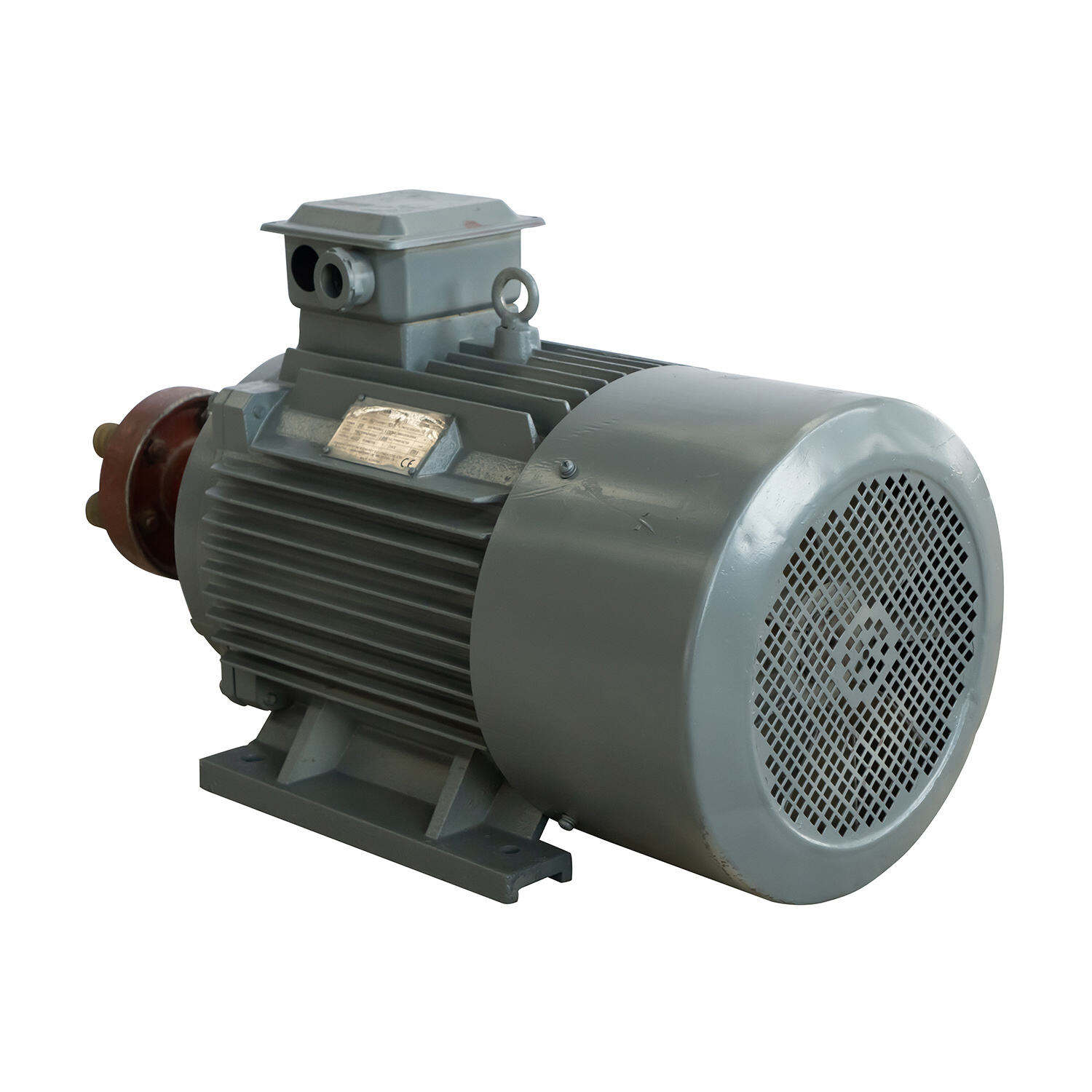
Configuring a VFD Compatible Motor for compressor service requires setting dynamic current limit ceilings that absorb rapid pressure spikes without generating nuisance faults. For an Air Compressor PMSM, the continuous operational current limit should be configured between 120% and 150% of nominal rating, while the instantaneous peak current clamp is set between 200% and 250% for durations under two seconds. Setting these thresholds prevents excessive current draw while enabling the Air Compressor PMSM to push through peak compression strokes.
Torque limits must be coordinated with the physical demagnetization curve of the Air Compressor PMSM. Modern digital inverters calculate real-time d-axis and q-axis currents, preventing the stator from injecting excessive demagnetizing field components into the rotor. This coordinated control preserves synchronous magnetic alignment in the Air Compressor PMSM, allowing steady torque delivery without risking magnetic degradation during aggressive pressure fluctuations.
Dynamic Acceleration Profiling and Thermal Memory Configuration
Starting an Air Compressor PMSM against residual system pressure requires tuned acceleration ramping. An overly rapid acceleration ramp creates immense starting current transients, whereas an overly sluggish ramp causes the Air Compressor PMSM to stall before achieving stable discharge pressure. Implementing an S-curve acceleration profile allows the Air Compressor PMSM to break away smoothly, synchronizing rotor poles before ramping up to operational speed.
Furthermore, electronic overload protection must incorporate an active thermal memory algorithm. In high-cycle reciprocating applications categorized under IEC 60034-1 as duty class S4 or S6, an Air Compressor PMSM experiences repeated thermal pulses from frequent starts and stops. Enabling thermal memory ensures that the drive tracks cumulative heat dissipation over multiple cycles rather than resetting thermal counters after every shutdown, preventing cumulative overheating in the Air Compressor PMSM.
ENNENG motor products are engineered across unified voltage ratings from 110V to 690V and unified power ratings from 5kW to 5MW, providing heavy-duty drive solutions for demanding compression applications. For remote off-grid monitoring stations and distributed clean energy installations, ENNENG also provides vertical axis wind turbine systems rated from 1kW to 10kW, emphasizing 3kW, 5kW, and 10kW platforms to ensure dependable utility generation.
Engineering Consultation and Drive Protection Inquiries
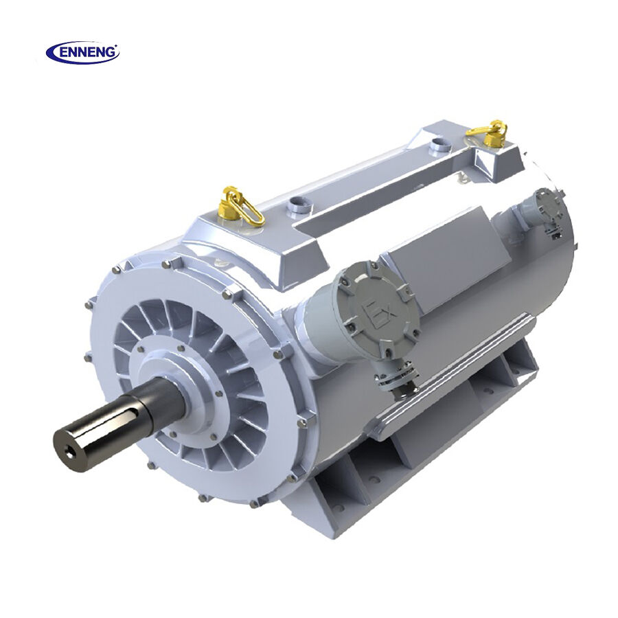
Establishing an optimized protection scheme for an Air Compressor PMSM requires evaluating compressor compression cycles, peak torque ratios, and plant electrical distributions. Upgrading compressor assets with an advanced Air Compressor PMSM reduces electricity consumption, eliminates pressure hunting, and delivers continuous mechanical reliability under severe impact loading. Technical specialists provide comprehensive torsional vibration modeling, inverter parameter matching, and complete turnkey drive engineering. Reach out to application specialists today to analyze plant compression requirements and receive customized drive protection guidance.
- WhatsApp: +86 18562780228
- E-Mail: [email protected]
- Phone: +86 532 66000559
FAQ
Q: How does an Air Compressor PMSM prevent irreversible demagnetization during impact loads?
A: An Air Compressor PMSM utilizes high-coercivity UH or EH series rare-earth permanent magnets capable of withstanding operating temperatures up to 180°C without flux decay. Additionally, the variable frequency drive implements fast vector control algorithms that continuously calculate demagnetizing current vectors. Clamping transient peak current below the magnet demagnetization knee ensures that high-torque impact loads never degrade magnetic performance.
Q: Why is direct winding temperature monitoring essential for an Air Compressor PMSM?
A: Because an Air Compressor PMSM has lower rotor thermal mass than a standard induction machine, repetitive impact loads generate localized thermal spikes faster than external current sensors can detect. Embedding PT100 temperature detectors directly within stator end-windings provides instantaneous thermal feedback. This direct measurement ensures the drive triggers thermal warnings and controlled shutdowns before excessive heat damages winding insulation or degrades rotor magnets.
Q: What encoder or feedback precautions are required for an Air Compressor PMSM in high-vibration service?
A: Severe reciprocating compressor shock loads can fracture delicate glass discs inside standard optical encoders. An Air Compressor PMSM operating under impact conditions should utilize a rugged magnetic resolver or heavy-duty inductive encoder. Furthermore, feedback cables must feature braided shielding grounded at the inverter end and maintain physical separation from motor power leads to prevent electromagnetic noise from corrupting rotor position signals.

