Industrial Thermal Realities and Permanent Magnet Vulnerabilities
Permanent magnet synchronous motors deliver extraordinary energy density and torque performance across modern manufacturing plants. In an industrial ceramic tile production facility operating continuous kiln exhaust exhausters, a newly installed drive began drawing twenty-five percent more electrical current after five months of operation while struggling to achieve nominal operating torque. Diagnostic testing revealed that ambient exhaust radiant heat, combined with continuous harmonic current overloads, had elevated rotor core temperatures beyond 165 degrees Celsius, triggering irreversible magnetic demagnetization in the rare-earth magnetic steel. Operating a Permanent Magnet Motor PMSM in severe thermal environments requires deep engineering comprehension of the physical mechanisms that threaten magnetic domain alignment.
|
Magnet Material Grade
|
Max Continuous Operating Temp
|
Curie Temperature
|
Thermal Demagnetization Resistance
|
|
Standard N Series NdFeB
|
80°C
|
~310°C
|
Low (Unsuitable for Heavy Industry)
|
|
High Temperature H Series
|
120°C
|
~320°C
|
Moderate (Light Industrial Applications)
|
|
Super High SH Series
|
150°C
|
~340°C
|
High (Standard Industrial Duty)
|
|
Ultra High UH / EH Series
|
180°C - 200°C
|
~360°C
|
Exceptional (Heavy Industrial Severe Duty)
|
Rare-earth neodymium iron boron (NdFeB) permanent magnets possess high remanence (Br) and magnetic energy product (BHmax). However, their intrinsic magnetic coercivity (Hcj)—the physical resistance to demagnetization—exhibits a negative thermal coefficient typically ranging between -0.5% and -0.7% per degree Celsius. As operating temperatures climb, the linear demagnetization curve bends, creating an inflection point known as the “knee point”. If operating conditions push the magnetic working point below this knee point, irreversible loss of magnetic flux occurs, permanently degrading motor torque capability and elevating operating current.
Intersection of Elevated Thermal Rise and Armature Reaction Fields
High temperature alone rarely triggers catastrophic demagnetization in well-designed machinery; rather, it drastically narrows the safety margin against opposing electromagnetic fields. In a Permanent Magnet Motor PMSM, the magnetic flux generated by stator armature currents directly opposes the magnetic field of the rotor magnets along the direct (d-axis) pathway. Under normal temperatures, the magnet withstands this opposing field. However, when ambient temperatures elevate rotor core heat, the magnet’s intrinsic coercivity drops significantly. A sudden overload current or heavy starting inrush produces an armature reaction field that drives the magnetic working point below the knee point, causing permanent demagnetization.
Uncontrolled Inverter Carrier Harmonics and Rotor Eddy Currents
Operating permanent magnet motors on variable frequency inverters introduces high-frequency pulse-width modulated (PWM) voltage harmonics. These harmonic voltages penetrate the motor air gap and induce high-frequency eddy currents directly within the conductive rare-earth magnetic steel. Because the rotor operates inside a sealed enclosure with limited convective heat transfer, eddy currents generate localized hot spots directly within the magnets. In a Permanent Magnet Motor PMSM lacking segmented magnet construction, localized temperatures can exceed surface temperature measurements by 20 to 40 degrees Celsius, triggering localized demagnetization.
Aggressive Field-Weakening Control at High Rotational Speeds
Extending the operating speed of a permanent magnet motor above its nominal base speed requires the inverter to command negative d-axis demagnetizing current (id). This commanded current actively suppresses net air gap flux to lower motor back-EMF, allowing higher shaft speeds. In high-ambient environments where the motor is already operating near its thermal rating, aggressive field weakening exerts continuous electromagnetic demagnetizing pressure directly against hot magnets. If the drive loses inverter control synchronization or suffers a transient power interruption during high-speed field weakening, uncontrolled current surges can permanently destroy rotor magnetic strength.
Thermal Resilience and Design Excellence of ENNENG PMSM Motors
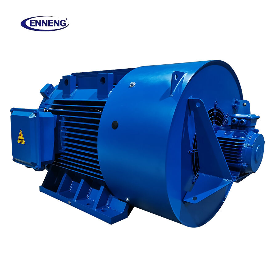
Preventing thermal demagnetization requires rigorous electromagnetic modeling and conservative material selection. ENNENG manufactures heavy-duty synchronous permanent magnet motors engineered to withstand severe thermal, electrical, and mechanical stresses. Integrating an ENNENG Permanent Magnet Motor PMSM into demanding production lines guarantees absolute magnetic permanence across voltages spanning 110V to 690V.
|
Engineering Factor
|
Generic Commercial PM Motor
|
ENNENG Industrial PMSM
|
|
Magnetic Material Selection
|
Standard N or M Grade NdFeB
|
Premium SH, UH, or EH Grade NdFeB
|
|
Operating Temperature Rise
|
Class F (105K) Exhaustion
|
Lower than 60K (Class B Reserve)
|
|
Magnet Lamination Strategy
|
Solid Bulk Magnets
|
Precision Segmented & Insulated Magnets
|
|
Thermal Sensing Topology
|
Single Stator Thermostat
|
Tri-Axis Embedded PT100 RTD Sensors
|
The unified engineering framework developed by ENNENG covers broad capacities from 5kW up to 5MW multi-megawatt systems, with complete voltage versatility ranging from 110V to 690V. Operating with an internal temperature rise below 60K ensures a massive thermal safety buffer, keeping rotor magnets safely separated from their critical demagnetization thresholds under severe ambient heat.
Dysprosium and Terbium Micro-Alloying for High Coercivity
ENNENG utilizes premium sintered NdFeB magnets formulated with dysprosium (Dy) and terbium (Tb) heavy rare-earth grain boundary diffusion. This metallurgical process dramatically elevates the magnet’s intrinsic coercivity (Hcj) without sacrificing remanence, allowing continuous operation at temperatures exceeding 180 degrees Celsius. In an ENNENG Permanent Magnet Motor PMSM, the magnetic knee point remains firmly confined to the third quadrant of the B-H curve, ensuring that transient electrical overloads cannot induce permanent flux degradation.
Rotor Magnet Segmentation and Internal Ventilation Circuits
To eliminate localized eddy current overheating, ENNENG incorporates axial and circumferential magnet segmentation. Isolating individual magnet segments with microscopic epoxy barriers suppresses circulating eddy current loops, reducing rotor iron losses by up to sixty percent. Furthermore, rotor carcasses incorporate internal aerodynamic ventilation channels that circulate cooling air directly across the magnet retention sleeves, maintaining uniform rotor temperature distribution.
Authoritative Standards and Thermal Verification Frameworks
Industrial motor thermal classification and demagnetization testing must conform to rigorous international engineering standards. Motor thermal performance and insulation endurance are governed by IEC 60034-1, which defines standard Class B, Class F, and Class H temperature rise limits.
Dielectric testing and loss-segregation must adhere to IEC 60034-2-1 standards. To verify magnetic permanence under fault conditions, motor designs must comply with IEC 60034-14 vibration criteria and IEEE 841 severe-duty petroleum and chemical industry standards. Verification of demagnetization resistance requires testing the Permanent Magnet Motor PMSM under sudden symmetrical three-phase short-circuit conditions at maximum operating temperature per IEEE 115 protocols, ensuring no irreversible flux loss occurs. Furthermore, electrical installation safety and thermal overload protection must satisfy NFPA 70 National Electrical Code Article 430.
Field Maintenance and Thermal Protection Guidelines
Protecting permanent magnet investments requires disciplined field monitoring and systematic preventative maintenance procedures.
Advanced Thermal Sensor Integration and Trip Calibration
Never operate a permanent magnet motor in hot industrial environments without active thermal protection. Verify that embedded PT100 resistance temperature detectors (RTDs) are wired into drive safety interlocks. Program the variable frequency controller to issue an alarm warning at 110 degrees Celsius and execute an immediate controlled shutdown if stator temperatures reach 130 degrees Celsius, well below the thermal limits of premium NdFeB grades.
Inspecting Cooling Air Passages and Blower Performance
Conduct monthly inspections of external motor cooling cowls, radiator fins, and auxiliary cooling fans. In dusty industrial environments like cement plants, textile mills, and chemical facilities, particulate buildup acts as thermal insulation, choking convective heat transfer and elevating rotor core temperatures. Regularly clean cooling airways using dry compressed air and confirm that auxiliary cooling fan motors rotate in the correct direction.
Field Verification of Demagnetization via Back-EMF Testing
If a Permanent Magnet Motor PMSM begins drawing abnormal operating current or repeatedly trips drive overload protection, perform a back-EMF verification test. Disconnect the motor from driven equipment and spin the shaft at nominal rated speed using an auxiliary drive or lathe. Measure line-to-line open-circuit terminal voltage using a calibrated digital oscilloscope. If the measured back-EMF voltage is more than 5 percent below the factory nameplate value, irreversible demagnetization has occurred, requiring rotor refurbishment.
To review specialized permanent magnet motor designs and thermal specifications, explore the ENNENG Products Catalog and review solutions via ENNENG Motor Engineering.
For technical inquiries regarding high-temperature motor selection or demagnetization risk mitigation, contact ENNENG:
FAQ
Q: How can plant technicians determine if a Permanent Magnet Motor PMSM has demagnetized?
A: The primary operational symptom of demagnetization is a steady increase in motor current consumption to produce the same mechanical torque, accompanied by elevated operating temperatures and frequent drive overload trips. To confirm, uncouple the motor and spin it at rated speed to measure open-circuit line-to-line back-EMF voltage. A voltage drop exceeding 5 percent compared to nameplate ratings confirms permanent demagnetization.
Q: What is the difference between reversible and irreversible magnet demagnetization?
A: Reversible demagnetization occurs when elevated temperature causes a temporary drop in magnetic flux, but the working point remains above the knee point of the B-H curve. When the motor cools, full original magnetic strength returns. Irreversible demagnetization happens when heat and an opposing armature magnetic field push the working point past the knee point, permanently destroying internal magnetic domain alignment.

 EN


