In chemical circulation loops, municipal water desalination plants, district heating networks, and paper mill stock preparation lines, centrifugal pumps operate 6,000 to 8,760 hours per year to transport massive volumes of industrial fluids. Fluid systems engineers auditing plant electricity consumption frequently discover that pumping systems consume 25% to 40% of total factory electrical power—yet operate far below optimal wire-to-water efficiency. When conventional squirrel-cage induction motors drive centrifugal pumps across fluctuating daily flow demands, heavy rotor slip losses, throttling valve pressure drops, and poor partial-load power factors waste thousands of kilowatt-hours every month.
A centrifugal pump system converts electrical grid input into hydraulic flow and head through a tightly coupled chain of electronic control, electromagnetic torque conversion, and impeller hydrodynamics. Relying on legacy IE2 or IE3 asynchronous motors—which suffer steep efficiency declines whenever flow throttles back—caps the overall efficiency of the fluid-transport process. Upgrading to an ultra-premium Centrifugal Pump Motor IE5 from ENNENG eliminates rotor excitation losses and synchronizes seamlessly with variable-speed hydraulic curves, elevating wire-to-water efficiency across the entire operating envelope.
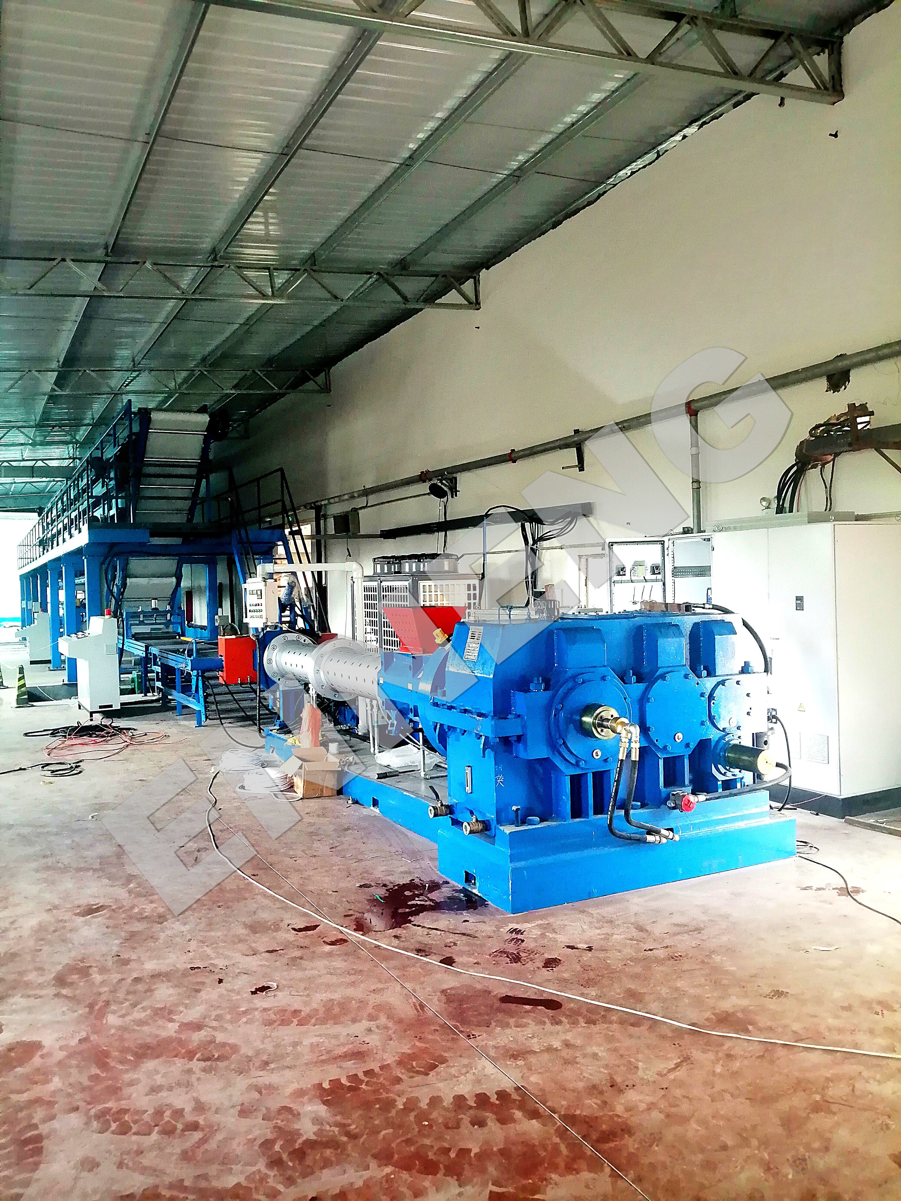
Technical Highlights: Electromagnetic Synergy with Centrifugal Pump Hydraulics
The Affinity Laws and Partial-Load Penalties of Asynchronous Pump Motors
Centrifugal pumps are variable-torque hydrodynamic machines governed by the Pump Affinity Laws: volumetric flow varies linearly with shaft speed, head varies with the square of speed, and shaft power varies with the cube of speed. Because industrial fluid processes rarely require 100% peak design flow continuously, variable frequency drives (VFDs) routinely reduce pump speed to 60%–80%, dropping mechanical shaft torque load to 35%–60%. In a conventional asynchronous induction motor, stator windings must continue drawing high fixed reactive magnetizing current (30% to 45% of rated amps) even when hydraulic load drops to 40%—causing motor efficiency and power factor to plummet right in the zone where the pump spends most of its operating life.
Zero Rotor Loss and Flat Efficiency Plateau of the Centrifugal Pump Motor IE5
An ENNENG Centrifugal Pump Motor IE5 utilizes a permanent magnet synchronous rotor to match the variable-torque physics of centrifugal fluid transport:
-
30%–40% Lower Motor Losses Than IE3 (20% Below IE4): Classified at the highest ultra-premium tier under IEC 60034-30-1 and IEC TS 60034-30-2, the Centrifugal Pump Motor IE5 eliminates induced rotor cage copper losses (I2R) entirely.
-
Flat Efficiency Curve Across Variable Flow Rates: Without fixed rotor magnetizing current penalties, the motor maintains peak-level electrical efficiency from 25% partial load up to 100% full hydraulic head.
-
Zero-Slip Hydraulic Head Precision: Synchronous locking between the permanent magnet rotor and VFD frequency prevents load-induced speed slip, maintaining exact discharge pressure and flow setpoints without hunting.
|
Fluid-Transport Performance Metric
|
Standard IE3 Asynchronous Pump Motor
|
ENNENG Centrifugal Pump Motor IE5
|
|
International Efficiency Class
|
Premium Efficiency (IE3)
|
Ultra-Premium Efficiency (IE5)
|
|
Total Motor Energy Loss Reduction
|
Baseline Reference Loss (100%)
|
30% to 40% Lower Total Motor Losses
|
|
Partial-Load Efficiency (30%–60% Flow)
|
Drops Sharply Due to Fixed Magnetizing Draw
|
Remains Flat and High Across Partial Loads
|
|
Power Factor at Reduced Pump Flow
|
Degrades to 0.60 – 0.78
|
Maintains 0.95 to 1.00 Near-Unity PF
|
|
Speed-to-Flow Regulation
|
Asynchronous (1%–3% Rotor Slip Drift)
|
Strictly Synchronous (0% Rotor Slip)
|
|
Unified Voltage Range
|
Fixed Single-Voltage Winding
|
110V–690V Unified Voltage Range
|
Core Advantages of ENNENG Centrifugal Pump Motor IE5 Systems
Maximizing Wire-to-Water Efficiency Across 110V–690V Pump Stations
True pumping economy is measured by specific energy consumption (kWh per cubic meter of fluid pumped). Engineered across a unified voltage range of 110V–690V, an ENNENG Centrifugal Pump Motor IE5 pairs with closed-loop PID pressure or flow controllers to eliminate mechanical throttling valves completely. Because the motor operates with a 0.95 to 1.00 power factor and 15K–20K lower temperature rise, stator line current drops by over 10%—reducing upstream feeder cable losses and extending mechanical pump seal and bearing life through cooler shaft conduction. Beyond industrial fluid-transport drives, ENNENG applies this ultra-efficient permanent magnet engineering to generators across a unified 5kW–5MW power range (110V–690V) for hydro recovery and waste-heat skids, plus vertical axis wind turbines spanning 1kW–10kW (focusing on 3kW, 5kW, and 10kW models).
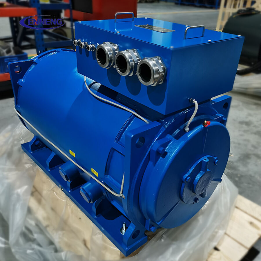
Complying with IEC TS 60034-30-2, EN 16480, and ISO 9906 Standards
Modern industrial pump installations must satisfy strict system-level energy and hydraulic test codes. Specifying an ENNENG Centrifugal Pump Motor IE5 verified under IEC TS 60034-30-2 (variable-speed AC motor efficiency at seven standardized torque-speed points) and IEC 61800-9-2 (Power Drive System IES2 efficiency) directly boosts the Extended Product Approach (EPA) Energy Efficiency Index (EEI) defined under European standard EN 16480 for rotodynamic water pumps. Furthermore, zero-slip synchronous speed stability simplifies hydraulic acceptance testing under ISO 9906 Grade 1 and Grade 2 tolerances by eliminating motor slip corrections during flow-head curve verification.
Industrial Application Scenarios and Engineering Maintenance Guide
1. End-Suction Process Pumps, Multistage Boosters, and Split-Case Circulation Pumps
In chemical batch transfer, reverse-osmosis high-pressure feed pumps, and HVAC district cooling loops, replacing throttled IE3 induction drives with an ENNENG Centrifugal Pump Motor IE5 cuts specific kilowatt-hour consumption per cubic meter by 15% to 35% while preventing cavitation-induced thermal trips.
2. Practical Selection, Inspection, and Maintenance Protocols
To achieve maximum wire-to-water efficiency when deploying a Centrifugal Pump Motor IE5 in industrial fluid networks, follow these engineering guidelines:
-
Align Motor Rating with the Best Efficiency Point (BEP): Size the Centrifugal Pump Motor IE5 to match the pump impeller's hydraulic Best Efficiency Point (BEP) and maximum run-out flow power rather than compounding excessive OEM safety margins.
-
Configure VFD Quadratic Variable-Torque V/f or MTPA Curves: Program the paired VFD controller for centrifugal quadratic torque load profiles using Maximum Torque Per Ampere (MTPA) optimization to minimize stator current during low-flow standby hours.
-
Verify Laser Coupling Alignment on Close-Coupled or Long-Coupled Skids: Use precision laser alignment on B3 foot-mounted or B35 foot-and-flange mounted pump skids to prevent radial shaft deflection from wearing mechanical stuffing-box seals.
-
Set Dry-Run Under-Load Torque Protection: Utilize the linear current-to-torque relationship of the Centrifugal Pump Motor IE5 on the VFD to detect sudden torque drops caused by dry running or suction strainer blockage, shutting down the pump before mechanical seals burn out.
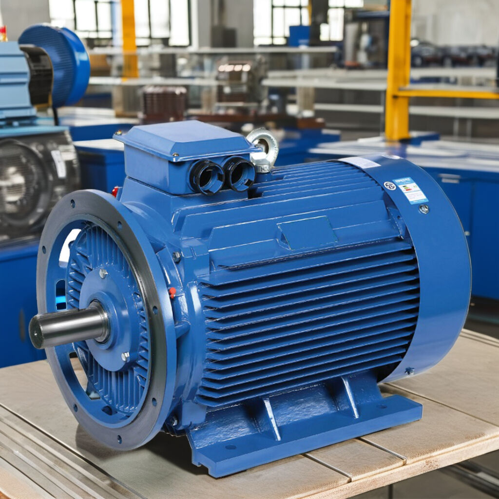
The ENNENG Customisation Advantage
Industrial pump OEMs and plant retrofitters require diverse mounting configurations—from vertical hollow-shaft/solid-shaft V1/B5 flanges for inline multistage boosters to heavy horizontal B3 cast-iron frames for split-case pumps. ENNENG custom-engineers its Centrifugal Pump Motor IE5 series across the unified 110V–690V range with drop-in IEC 60072 dimensions, anti-corrosion chemical coatings, and reinforced axial thrust bearings.
Contact ENNENG Today.
Consult the ENNENG pump drive engineering team to evaluate your hydraulic duty points and receive a customised Centrifugal Pump Motor IE5 proposal.
FAQ
Q: Why does a Centrifugal Pump Motor IE5 deliver much higher real-world energy savings than an IE3 motor on variable-flow pumps?
A: Centrifugal pumps spend most of their operating hours throttled back between 40% and 75% flow, where mechanical shaft load drops steeply. At these partial loads, an IE3 induction motor wastes heavy reactive current magnetizing its rotor cage, whereas an ENNENG Centrifugal Pump Motor IE5 uses lossless permanent magnets to maintain ultra-high efficiency across the entire flow range.
Q: How does an ENNENG Centrifugal Pump Motor IE5 improve hydraulic pressure stability in automated fluid lines?
A: Asynchronous induction motors experience 1% to 3% rotor speed slip whenever fluid viscosity or back-pressure fluctuates, causing discharge head to drift. Because an ENNENG Centrifugal Pump Motor IE5 locks synchronously to the VFD output frequency with zero slip, impeller RPM and hydraulic pressure remain rock-steady under changing process demands.
Q: What voltage and power generation capacities does ENNENG offer alongside IE5 pump motors?
A: ENNENG manufactures its Centrifugal Pump Motor IE5 series across a unified voltage range of 110V–690V to fit global pumping stations. For industrial power generation and hydraulic energy recovery turbines, ENNENG also produces permanent magnet generators across a unified 5kW–5MW power range and vertical axis wind turbines spanning 1kW–10kW (focusing on 3kW, 5kW, and 10kW models).

 EN


