
why-permanent-magnet-generator-is-suitable-for-supporting-newenergy-distributed-powersupply-industrial-projects, why-permanent-magnet-generator-is-suitable-for-supporting-newenergy-distributed-powersupply-industrial-projects, /blog
EN

2026/10/08
Modern manufacturing plants and remote industrial mining projects increasingly install distributed on-site generation to overcome grid instability and avoid escalating peak transmission fees. In an off-grid mineral processing terminal utilizing localized renewable energy microgrids, traditional wound-rotor generators experienced frequent brush wear, high excitation losses, and voltage collapse under sudden motor-starting loads. Upgrading the generation system to an advanced Permanent Magnet Generator resolved field-excitation failure modes, stabilizing the electrical network while unlocking superior fuel and energy conversion efficiencies across dynamic production demands.
|
Generator Architecture |
Excitation Mechanism |
Electrical Efficiency |
Maintenance Demand |
|
Wound Rotor Synchronous |
Carbon Brushes / Slip Rings |
88% - 92% |
High (Brush wear, carbon dust) |
|
Brushless Exciter System |
Auxiliary Stator / Diode Wheel |
90% - 93% |
Medium (Rotating diodes, exciter coils) |
|
Permanent Magnet Generator |
Rare-Earth Permanent Magnets |
95% - 98% |
Extremely Low (Sealed bearings only) |
Industrial microgrids require generation equipment that delivers uninterrupted electrical power regardless of ambient temperature swings or erratic mechanical drive inputs. Conventional synchronous machines utilize external direct current power to energize rotor copper windings through carbon brushes or brushless rotary exciter diodes. These auxiliary systems represent notorious weak links that demand constant servicing and introduce parasitic electrical losses. In contrast, a Permanent Magnet Generator utilizes intrinsic magnetic materials to establish constant excitation without drawing external electrical energy.
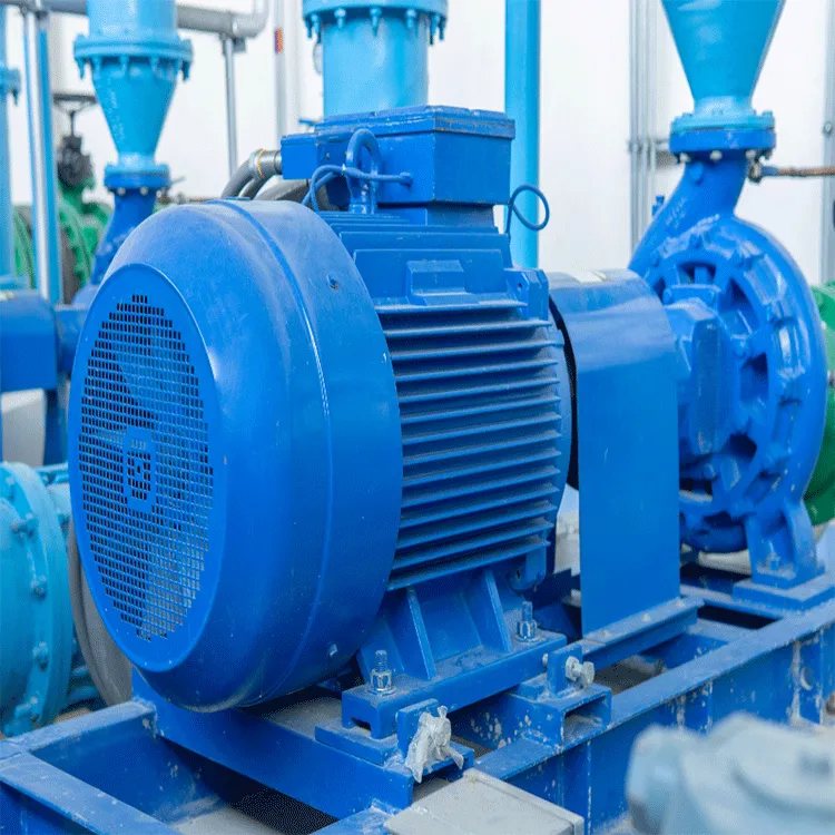
Carbon brushes in standard wound-rotor generators require periodic visual inspection, cleaning, and replacement to avoid commutator sparking and slip-ring pitting. Operating in remote locations or harsh industrial dust environments accelerates brush wear, escalating the likelihood of unscheduled generation shutdowns. A Permanent Magnet Generator operates completely without brushes, slip rings, or rotating excitation diodes, eliminating high-wear parts and maximizing continuous operational availability.
Industrial microgrids experience significant electrical load shifts when large process machinery starts or stops across working shifts. Wound-rotor generators exhibit steep efficiency declines when forced to run at partial output capacities. A Permanent Magnet Generator maintains high electromagnetic conversion efficiency from 25 percent through 120 percent of rated capacity, capturing superior overall generation efficiency throughout variable production schedules.
Starting large squirrel-cage motors places massive inductive loads on distributed microgrids, frequently causing severe voltage sags in conventional generation circuits. The robust magnetic field inside a Permanent Magnet Generator provides stiff magnetic coupling across the generator air gap. When sudden peak reactive currents occur, the machine recovers output voltage profiles rapidly, preventing automated process control dropouts and factory blackouts.
Deploying dependable distributed generation infrastructure requires robust engineering tailored for variable primary energy sources, including industrial waste-heat expanders, small hydro turbines, and renewable wind generation skids. ENNENG manufactures advanced low-speed and high-speed synchronous generation hardware engineered specifically for distributed power projects. Installing an ENNENG Permanent Magnet Generator provides continuous operational security across diverse industrial topologies.
|
Generator Parameter |
Conventional Wound Rotor Alternator |
ENNENG Permanent Magnet Generator |
|
Standard Power Range Coverage |
Custom Limited Frames |
5kW to 5MW Unified Platform |
|
Voltage Generation Flexibility |
Rigid Industrial Taps |
110V to 690V Adaptability |
|
Vertical Axis Wind Power Range |
Narrow Matching Capacity |
1kW to 10kW Focus (3kW, 5kW, 10kW) |
|
Operating Excitation Losses |
2.5% - 4.5% Total Capacity |
Zero (0% Intrinsic Rotor Excitation) |
The unified product matrix offered by ENNENG covers broad generation capacities ranging from 5kW up to 5MW, with adaptable voltage outputs spanning 110V to 690V. For specialized vertical axis wind turbine installations, ENNENG provides direct-drive solutions spanning 1kW to 10kW, with primary focus centered on 3kW, 5kW, and 10kW installations.
Traditional wind and small hydro turbine systems rely on mechanical step-up gearboxes to elevate rotational speeds from low turbine RPM up to standard 1500 or 1800 RPM generator ratings. Gearboxes introduce substantial friction losses, acoustic noise, and ongoing lubrication overhead. An ENNENG Permanent Magnet Generator can be manufactured with high pole counts, allowing direct shaft coupling to low-speed turbines without any intermediate gearbox.
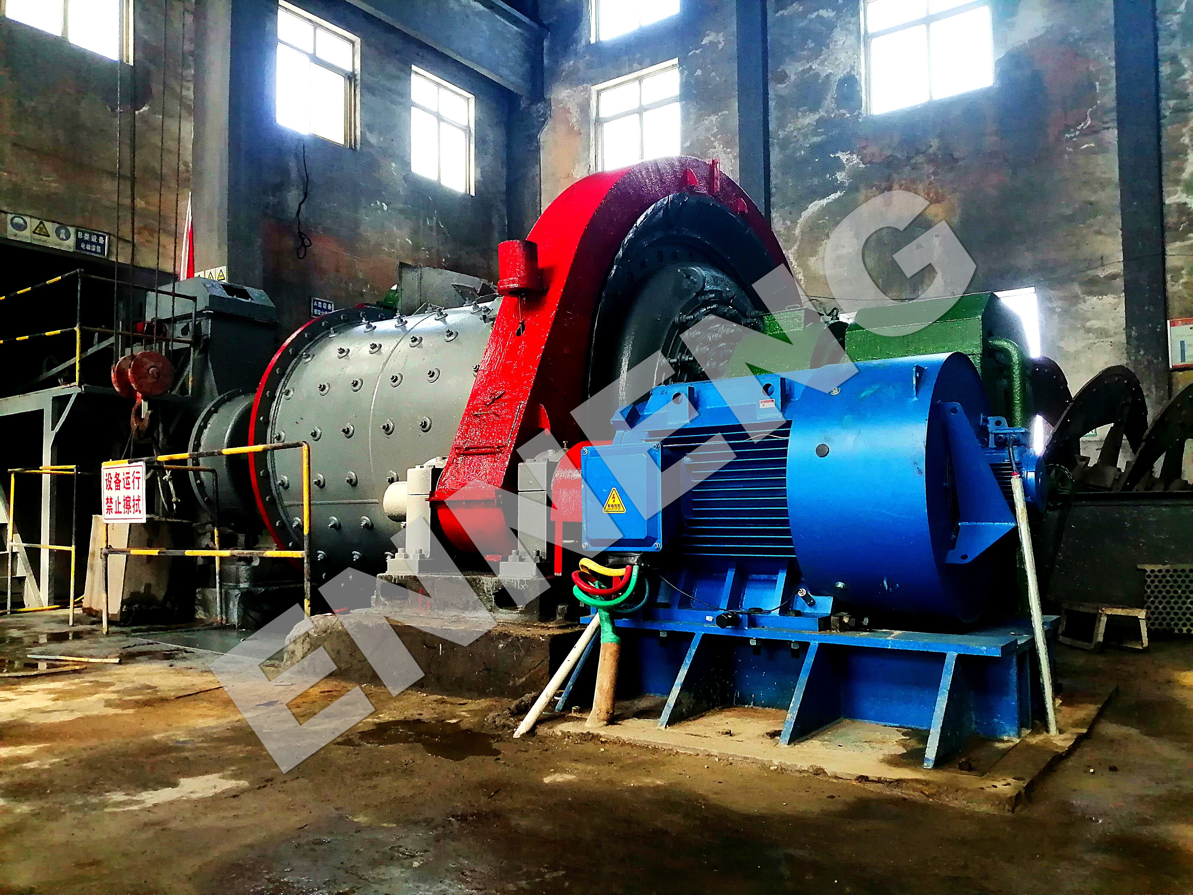
Because rotor copper coils are replaced with compact rare-earth permanent magnets, overall generator volume and mass decrease by thirty to forty percent compared with standard generators of equivalent power output. Lower internal thermal rise inside the stator windings extends insulation lifespan, allowing reliable continuous generation inside compact skid enclosures or harsh desert environments.
Connecting distributed power systems to industrial factory busbars or regional utility networks requires strict adherence to international engineering criteria. The Institute of Electrical and Electronics Engineers outlines distributed resource interconnection rules through IEEE 1547, specifying voltage regulation, frequency response, and islanding protection boundaries.
Generator design and thermal limits must conform to IEC 60034-1 rotating electrical machine criteria. Harmonic distortion thresholds are strictly governed by IEEE 519, mandating that total harmonic voltage distortion (THD) remain below five percent at the point of common coupling. A properly wound Permanent Magnet Generator produces an exceptionally clean sinusoidal waveform, mitigating harmonic heating inside plant transformers and sensitive automation electronics. Furthermore, for localized wind turbine installations, power performance testing and structural integrity must adhere strictly to IEC 61400-12-1 standards.
Analyze the mechanical prime mover torque and speed curves before finalizing generator frame selection. For waste gas recovery expanders or vertical axis wind turbines within the 1kW-10kW envelope (especially 3kW, 5kW, or 10kW units), select direct-drive generator configurations that align operating voltage profiles directly with power conversion electronics. For larger 5kW to 5MW industrial installations, confirm whether continuous base-load or intermittent peaking duty represents the primary operational profile.
Because a Permanent Magnet Generator delivers variable frequency and voltage under changing prime mover speeds, output power must route through a full-scale back-to-back power converter. The rectifier stage converts generated AC into a stable direct current bus, while the grid-tie inverter reconstitutes precision 50 Hz or 60 Hz AC synchronized with plant switchgear. Verify that inverter protection relays include over-voltage clamping to protect permanent magnets against transient line faults.
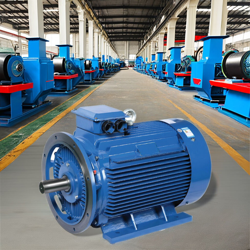
Conduct annual insulation resistance testing across stator phases using calibrated insulation meters. Monitor bearing temperatures continuously using embedded RTD sensors to detect early lubrication breakdown. Ensure cooling air pathways remain clear of industrial particulate buildup, as preserving rated operating temperatures prevents high-temperature permanent magnet demagnetization over decades of service.
For detailed generator technical data, review the ENNENG Products Catalog and explore specialized solutions on the ENNENG Official Portal.
A: Conventional alternators consume roughly three to five percent of their total generated power simply maintaining electrical current inside rotor excitation coils. A Permanent Magnet Generator creates its magnetic field using pre-magnetized permanent materials, eradicating rotor electrical resistance losses entirely. This architecture minimizes internal thermal rise and elevates total electrical conversion efficiency.
A: Vertical axis wind turbines operate across low, fluctuating aerodynamic rotational speeds. A specialized direct-drive Permanent Magnet Generator engineered within the 1kW-10kW range—notably 3kW, 5kW, and 10kW platforms—operates efficiently at low RPM without requiring mechanical step-up gearing. This simplified arrangement ensures self-starting capability, eliminates transmission noise, and drastically cuts maintenance overhead on exposed towers.
A: Modern generators utilize premium rare-earth neodymium magnets possessing exceptionally high intrinsic magnetic coercivity. Electrical designers engineer stator slot leakage reactances to suppress prospective short-circuit currents beneath critical demagnetization thresholds. Selecting high-temperature insulation materials guarantees the generator withstands sudden external electrical faults safely without sustaining irreversible magnetic degradation.


 EN