
 EN

Why Permanent Magnet Generator Heat Dissipation Matters in High-Power Industrial Generation
In a high-power plant, a Permanent Magnet Generator is not simply an efficient rotating machine with a compact footprint. It is a thermal system whose electrical output, magnet stability, insulation life, bearing condition, and availability all depend on how reliably heat leaves the active parts. As a renewable-energy engineer, I treat the cooling concept as an early specification decision, not a fan size selected after the electromagnetic design is complete.
This matters because a high-power Permanent Magnet Generator concentrates losses in less obvious places. Copper loss develops in the stator winding; iron loss develops in the core; eddy-current loss can affect conductive rotor parts; bearings, seals, and power electronics add their own heat. If the thermal path is weak at one of those points, a good efficiency figure at rated conditions may not translate into dependable continuous operation at the customer site.
Heat is a performance limit, not just a maintenance concern
Every Permanent Magnet Generator has an allowable temperature rise defined by its insulation system, materials, cooling method, duty cycle, and ambient condition. The important engineering question is therefore not “does it have cooling?” but “what temperature does each critical component reach during the actual load profile?” A machine that runs acceptably during a short factory test can behave very differently after hours of high torque, elevated ambient temperature, dust loading, or restricted airflow.
When winding temperature rises, conductor resistance rises too, which increases copper loss and creates a feedback loop. Higher temperatures can accelerate insulation aging and may reduce the margin available for overload events. In a Permanent Magnet Generator, rotor temperature deserves equal attention: magnet characteristics change with temperature, and the chosen magnet grade must retain adequate margin against irreversible demagnetization across credible operating and fault conditions.
Where heat originates in a high-power Permanent Magnet Generator
- Stator copper: current-driven I²R loss is often the dominant continuous heat source, especially where slot fill, end-winding geometry, and current waveform are demanding.
- Stator steel: hysteresis and eddy-current losses increase with electrical frequency and flux-density choices.
- Rotor assembly: magnet eddy losses, retaining-sleeve losses, and windage can become important at high speed.
- Mechanical parts: bearings, lubrication, seals, and couplings create heat that must not be ignored in a compact enclosure.
- System interfaces: rectifiers, converters, and nearby cabinets can raise inlet-air or coolant temperatures before the generator sees them.
A rigorous Permanent Magnet Generator thermal model maps these losses to real heat paths: winding-to-slot liner, winding-to-impregnation resin, core-to-frame, rotor-to-air gap, and frame-to-ambient or coolant. Treating the frame as a single uniform temperature hides the hot spots that most influence reliability.
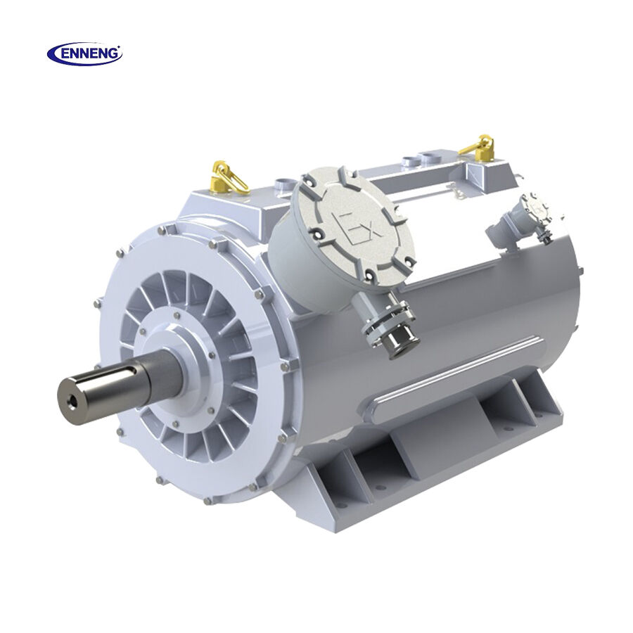
Why high power makes heat dissipation harder
Power scaling is not linear from a cooling perspective. As a Permanent Magnet Generator becomes more compact for a given output, active-material loading can increase faster than the available surface area for rejecting heat. High torque also means substantial electromagnetic loading, while high rotational speed may increase windage and rotor losses. The result is a design problem where electromagnetic, mechanical, and thermal decisions must be optimized together.
Industrial sites add another layer. A generator installed in a clean, conditioned room experiences a different thermal boundary from one in a wind turbine nacelle, marine enclosure, mining installation, or process plant. Ambient temperature, altitude, airborne contamination, water quality, maintenance access, vibration, and the number of annual full-load hours all influence whether air cooling remains appropriate or a liquid circuit becomes the more controlled option.
Choose the cooling architecture around the duty cycle
Forced-air cooling can be practical when the enclosure, ambient air quality, and service interval permit it. Its limitations become clearer when dust blocks passages, hot recirculated air reaches the inlet, or acoustic limits constrain fan operation. Closed-loop air-to-air or air-to-water arrangements isolate the internal circuit from harsh ambient air and provide more predictable conditions for a Permanent Magnet Generator.
Liquid cooling can remove heat closer to the stator and frame, often giving designers more flexibility in high-power-density applications. It also introduces water or glycol quality, leakage prevention, pump reliability, pressure drop, corrosion compatibility, and freeze protection as system requirements. The useful comparison is not air versus liquid in isolation; it is the complete availability, maintainability, and thermal-margin case for the application.
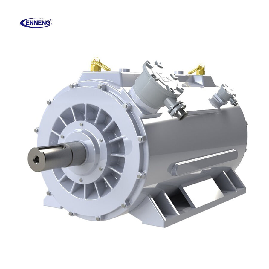
Protect magnets, windings, and bearings together
Thermal design should specify separate temperature limits and measurement locations for winding hot spots, stator core, coolant inlet and outlet, bearing housings, and—where feasible—rotor or magnet temperature estimates. A Permanent Magnet Generator cannot be protected well by a single frame sensor alone. The controls team needs meaningful alarms, derating logic, and shutdown thresholds tied to the components that actually govern life and demagnetization margin.
Good thermal contact is equally important. Impregnation quality, slot-liner selection, interface materials, end-winding support, and coolant-jacket geometry all affect the temperature gradient between copper and the cooling medium. In practice, a small construction detail can determine whether the measured frame temperature conceals a damaging winding hot spot.
Validate the design before field deployment
For an industrial Permanent Magnet Generator, validation should combine analytical loss calculations, thermal-network or CFD work where warranted, and representative temperature-rise testing. IEC 60034 provides a useful rotating-machine framework for rating, performance, and cooling-method terminology; the project specification should still define the actual ambient range, duty cycle, inlet conditions, overload events, and acceptance measurements.
Test plans should include stabilized rated operation, expected overload duration, reduced cooling capacity where credible, and hot-ambient scenarios. Correlating model predictions with measured winding and coolant temperatures helps the team refine design margin before a fleet installation. It also prevents an Energy Saving Motor Solution from being judged solely by peak efficiency while thermal reliability remains unproven.
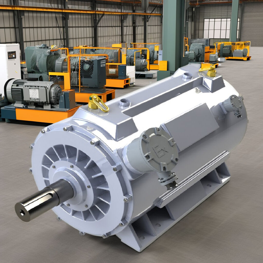
A practical specification checklist
- Define continuous, cyclic, overload, and fault duty—not only nameplate power.
- State ambient temperature, altitude, contamination class, enclosure constraints, and available cooling utilities.
- Request component-level temperature limits and predicted hot-spot temperatures for the Permanent Magnet Generator.
- Confirm the magnet material, temperature capability, and demagnetization-margin approach.
- Specify the cooling method, coolant conditions, filtration, service access, and alarm/derating strategy.
- Review temperature-rise test evidence using representative operating conditions.
The same discipline supports coordination with a Permanent Magnet Motor PMSM in a coupled drivetrain: thermal limits, cooling circuits, and converter behavior should be reviewed as one system rather than as separate catalog items. A capable High Efficiency Motor Supplier should be able to discuss these interfaces transparently, including what must be validated at the system level.
Engineering Consultation and System Integration
Upgrading high-vibration machinery with an advanced direct drive motor lowers plant acoustic noise, eliminates gearbox maintenance costs, and maximizes continuous operational reliability. Collaborating with an established high efficiency motor supplier guarantees proper low-speed torque sizing, verified torsional vibration modeling, and complete electrical drive package integration. Technical specialists perform detailed structural resonance analyses, acoustic surveys, and custom mechanical flange adaptations to modernize challenging industrial drivetrains. Inquire today to evaluate industrial equipment parameters and specify customized direct drive solutions.
- WhatsApp: +86 18562780228
- E-Mail: [email protected]
- Phone: +86 532 66000559
Conclusion
Effective heat dissipation is essential because it converts a Permanent Magnet Generator design from a high-efficiency concept into an industrially durable asset. By tracing losses, selecting cooling around the real duty cycle, protecting the winding and rotor separately, and validating temperatures under credible site conditions, project teams can preserve efficiency without sacrificing service life or availability.

