In metallurgical smelting plants, glass manufacturing furnaces, and chemical processing complexes, massive volumes of low-grade exhaust steam, hot process water, and flue gas are continuously vented into the atmosphere. Plant energy managers deploying Organic Rankine Cycle (ORC) expanders, screw expanders, or low-pressure steam turbines to convert this thermal waste into electricity often encounter disappointing kilowatt yields when utilizing conventional electrically excited synchronous or induction generators. Whenever upstream furnace loads fluctuate and expander shaft speeds drop, traditional generation skids suffer from steep efficiency penalties, exciter overheating, and mechanical step-up gearbox failures.
Low-temperature waste-heat recovery loops naturally operate with modest pressure differentials, producing low rotational speeds and variable torque at the turbine output shaft. Forcing a conventional four-pole generator to operate in this regime requires both a speed-increasing gearbox and continuous external excitation current—parasitic burdens that consume a substantial portion of the recovered thermal energy. Integrating an engineered Permanent Magnet Generator from ENNENG eliminates rotor excitation losses entirely and couples directly to low-speed expanders across a unified 5kW–5MW power range and 110V–690V voltage spectrum.
Technical Highlights: Overcoming Low-Speed Waste-Heat Bottlenecks
Parasitic Excitation Draws and Step-Up Gearbox Losses in Legacy Skids
Conventional electrically excited synchronous generators rely on copper field windings wrapped around the rotor core, energized either through carbon brushes and slip rings or an auxiliary brushless exciter armature. To generate terminal voltage at low rotational speeds, the automatic voltage regulator (AVR) must force high direct current through the rotor windings to maintain air-gap magnetic flux. This continuous excitation current generates substantial rotor copper loss (I2R), elevating internal rotor temperatures and consuming 3% to 8% of the generator’s gross electrical output. Furthermore, because standard four-pole generators must spin at 1500 RPM or 1800 RPM, coupling them to a slow-turning steam screw expander requires a speed-increasing gearbox that forfeits another 3% to 6% of mechanical power to high-speed gear mesh friction and oil churning.
Brushless Self-Excited Rotor Architecture of the Permanent Magnet Generator
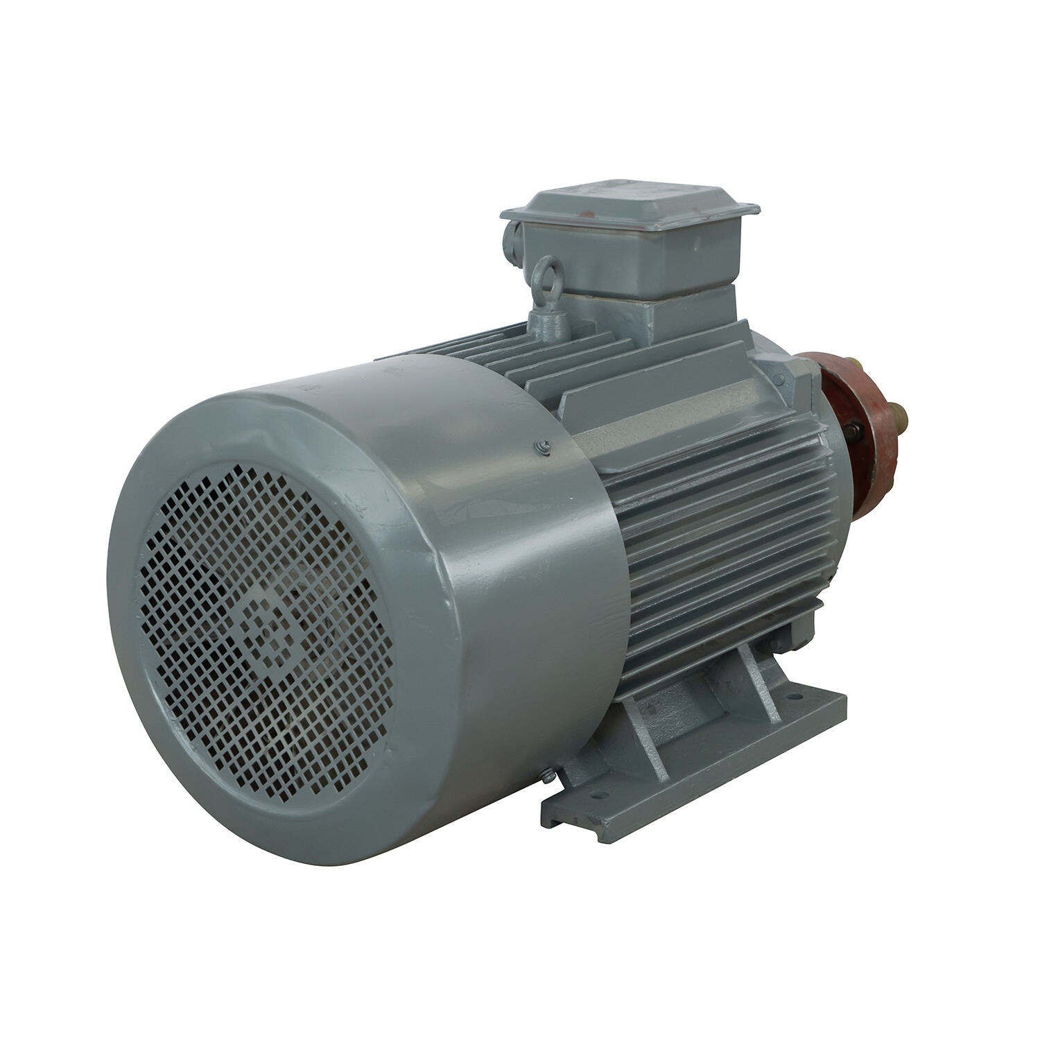
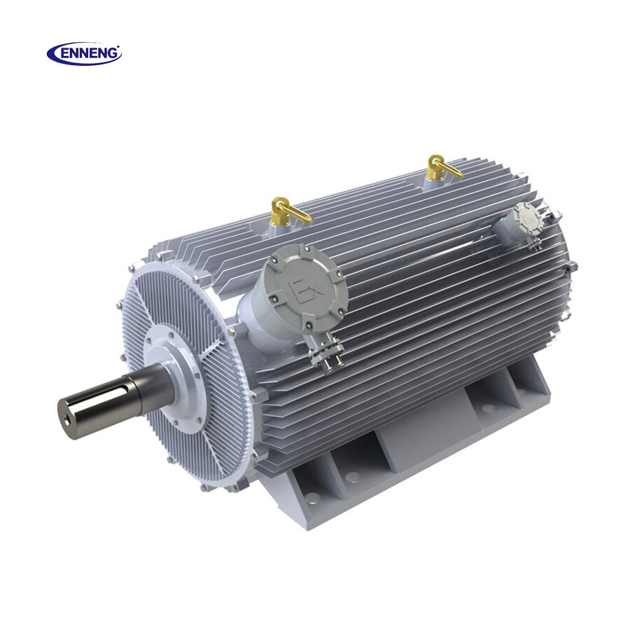
An ENNENG Permanent Magnet Generator replaces wound copper rotor coils, slip rings, and external DC exciters with high-coercivity permanent magnets precision-mounted within the rotor structure:
-
Zero Rotor Excitation Copper Loss: Because the magnetic field is permanently established by the rotor magnets, the Permanent Magnet Generator induces stator terminal voltage instantaneously upon shaft rotation without drawing a single watt of excitation power.
-
Direct Gearless Expander Coupling: Multi-pole stator and rotor geometries allow the Permanent Magnet Generator to match the native low RPM of screw expanders and radial-inflow turbines directly, eliminating step-up gearboxes and oil lubrication skids.
-
Superior Partial-Load Conversion Efficiency: When upstream boiler or furnace exhaust temperatures dip during off-peak factory shifts, the absence of fixed exciter losses allows the Permanent Magnet Generator to maintain high net electrical output across variable speeds.
Core Advantages of ENNENG Permanent Magnet Generator Systems
Wide Scalability Across 5kW–5MW and 110V–690V Networks
To accommodate the diverse thermodynamic profiles of industrial waste-heat streams, ENNENG designs its Permanent Magnet Generator portfolio across a unified generator power range of 5kW–5MW and a unified voltage range of 110V–690V. Whether recovering 50kW from a jacket-cooling water loop or 3MW from a petrochemical catalytic cracker flue-gas expander, the Permanent Magnet Generator maintains a high power factor and cooler internal winding temperatures across continuous 24/7 operation. Beyond industrial thermal recovery, ENNENG applies this exact low-speed permanent magnet generation physics to vertical axis wind turbine systems spanning 1kW–10kW, with a main focus on 3kW, 5kW, and 10kW models for distributed industrial microgrids.
Adhering to IEC 60034-1, IEC 60034-2-1, and IEC 60071 Standards
Industrial waste-heat power generation equipment connected to factory distribution grids must satisfy strict international electrotechnical codes. Every ENNENG Permanent Magnet Generator is engineered and tested in accordance with IEC 60034-1 for thermal rating and continuous duty performance, and IEC 60034-2-1 standard methods for determining losses and verified conversion efficiency. Furthermore, stator winding insulation systems are coordinated per IEC 60071 and ANSI/IEEE grid interconnection guidelines to withstand continuous operation alongside active front-end (AFE) rectifiers and grid-tie inverters, ensuring low total harmonic distortion (THD) and stable voltage delivery across 110V–690V plant networks.
Industrial Application Scenarios and Engineering Maintenance Guide
1. Saturated Steam Screw Expanders and ORC Turbine Skids
In chemical plants and steel sintering facilities, low-pressure saturated steam expanders frequently experience wet-steam two-phase flow and fluctuating shaft speeds between 300 RPM and 900 RPM. Coupling an ENNENG Permanent Magnet Generator directly to the expander shaft eliminates high-speed gearbox tooth fatigue caused by liquid slugging and maximizes continuous kilowatt recovery into the plant grid.
2. Practical Selection, Inspection, and Maintenance Protocols
Maximizing kilowatt-hour recovery and operational uptime in waste-heat power projects requires structured engineering practices:
-
Match Expander Speed-Torque Curves: Specify the Permanent Magnet Generator pole count and nominal voltage (within the 110V–690V unified range) to align precisely with the expander’s peak thermodynamic efficiency speed rather than forcing the turbine to match a fixed grid frequency.
-
Integrate Sinusoidal Inverter Filtering: When coupling the Permanent Magnet Generator to a back-to-back AC-DC-AC frequency converter, install dV/dt or sinusoidal harmonic filters to minimize high-frequency switching eddy currents on the rotor surface.
-
Inspect Shaft Thermal Isolation Barriers: Because waste-heat steam expanders operate at elevated temperatures, verify during quarterly inspections that thermal isolation couplings and bearing housing seals prevent conductive heat migration into the Permanent Magnet Generator drive-end bearing.
-
Monitor Stator RTD Temperature Trends: Log embedded PT100 resistance temperature detector (RTD) readings via the plant SCADA system to verify balanced three-phase loading and unobstructed cooling airflow.
The ENNENG Customisation Advantage
Waste-heat expanders vary widely in shaft flange dimensions, axial thermal expansion rates, and cooling media availability. ENNENG custom-engineers each Permanent Magnet Generator—offering air-cooled (IC411) or water-jacket-cooled (IC71W) enclosures, customized pole counts, and tailored voltage windings across 110V–690V and 5kW–5MW to match OEM turbine skids with zero mechanical rework.
Contact ENNENG Today.
Consult the ENNENG power generation engineering team to configure a customised Permanent Magnet Generator proposal for your waste-heat recovery project.
FAQ
Q: Why does a Permanent Magnet Generator outperform electrically excited generators in low-speed waste-heat systems?
A: Electrically excited synchronous generators require continuous DC current in the rotor windings to create a magnetic field, causing heavy copper heat losses that reduce net efficiency when waste-heat flow drops. An ENNENG Permanent Magnet Generator uses high-energy permanent magnets for self-excitation, eliminating rotor copper losses and brushes while delivering high conversion efficiency directly at low expander shaft speeds without a gearbox.
Q: What power and voltage ranges does ENNENG provide for industrial power generation projects?
A: ENNENG manufactures industrial Permanent Magnet Generator solutions across a unified power range of 5kW–5MW and a unified voltage range of 110V–690V, allowing seamless integration with small screw expanders up to multi-megawatt ORC turbines. Additionally, ENNENG produces vertical axis wind turbine systems rated from 1kW–10kW, focusing primarily on 3kW, 5kW, and 10kW units for hybrid renewable facilities.
Q: How does a gearless Permanent Magnet Generator connect to a fixed-frequency 50Hz or 60Hz factory grid?
A: Because a low-speed Permanent Magnet Generator rotates at the variable speed of the waste-heat expander, its variable-frequency AC output is routed through an industrial AC-DC-AC power electronics converter. The rectifier and grid-tie inverter synchronize the power precisely to the facility’s 50Hz or 60Hz busbar within the 110V–690V range, allowing the turbine to always spin at its most efficient thermodynamic speed.

 EN


