
 EN

Continuous mining slurry pump stations operating variable-flow transport lines 8,000 hours per year often experience severe line voltage drops and heavy utility penalty charges due to lagging reactive power. Operating engineers seeking electrical infrastructure relief frequently evaluate whether a Permanent Magnet Synchronous Motor provides true power-factor advantages over legacy induction units. Understanding the physical flux-generation mechanisms, excitation behavior, and inverter interactions reveals why permanent magnet technology resolves power quality bottlenecks across heavy industrial plants.
Traditional asynchronous motors draw substantial inductive magnetizing current directly from the plant distribution network to energize their rotor circuits, creating high phase displacement and parasitic thermal losses in upstream transformers. ENNENG supplies advanced drive solutions engineered with high-coercivity magnetic assemblies that eliminate inductive excitation demand, immediately raising system operating power factors and stabilizing plant bus voltages.
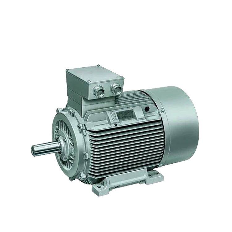
Physical Foundations of Excitation and Reactive Current Demand
Electrical distribution efficiency depends on how effectively alternating current converts into mechanical shaft torque without circulating non-productive reactive power. In standard industrial facilities, low operational power factor forces electrical substations, switchgear, and feeder cables to carry excessive apparent power, resulting in restricted thermal headroom and elevated utility demand penalties. Integrating a modern PM Synchronous Motor restructures electrical current dynamics at the motor terminals, replacing passive electromagnetic induction with permanent field excitation.
Magnetizing Current Mechanisms in Asynchronous Motors
A conventional three-phase asynchronous motor depends entirely on stator-supplied magnetizing current to establish the working air-gap magnetic flux. Because the rotor features no internal magnetic source, inductive excitation current lags the supply voltage by ninety electrical degrees, directly degrading operational power factor. Even when running uncoupled or lightly loaded, the induction motor continues drawing approximately thirty to fifty percent of rated current solely to maintain core magnetization. This persistent inductive demand causes the operating power factor of standard induction machines to plummet drastically to 0.30 or 0.50 during low-load intervals, forcing industrial plants to install bulky external capacitor banks.
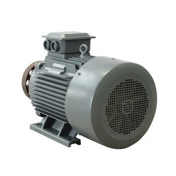
Flux Generation Architecture in Permanent Magnet Synchronous Motor Systems
A Permanent Magnet Synchronous Motor fundamentally alters this electromechanical relationship by embedding high-energy rare-earth neodymium-iron-boron magnets within the rotor core. These permanent magnets establish the working magnetic field autonomously without consuming reactive excitation current from the incoming alternating-current supply. Consequently, the stator windings draw current almost entirely in phase with the terminal voltage, focusing input energy on real torque generation rather than field excitation. Modern vector-controlled inverters dynamically maintain the stator current vector in precise quadrature with rotor magnetic flux, allowing a Permanent Magnet Motor PMSM to achieve operating power-factor values between 0.96 and 0.99 across broad speed ranges.
Power Factor Degradation Under Partial Loading and Direct Drive Operation
Industrial manufacturing processes rarely sustain continuous full-capacity operations, as cyclical process demands, variable batch sizes, and automated valve throttling regularly force machinery to operate at partial output. Evaluating how excitation architectures respond to changing mechanical loads is vital when specifying an effective energy saving motor solution for variable-duty industrial environments.
Partial-Load Reactive Demand and Phase Angle Displacement
When an induction machine experiences reduced mechanical loading, active current decreases in proportion to shaft torque while inductive magnetizing current remains largely constant. This disproportionate relationship causes the phase angle between voltage and current to widen, driving operational power factor down toward unacceptably poor levels. In contrast, an inverter-driven PM Synchronous Motor scales back both active current and total current draw while maintaining field alignment, preserving high power factor even at twenty-five percent load. Facilities operating variable-air volume ventilation fans or cyclic conveyor belts capture immediate energy conservation benefits because line currents decrease linearly with actual mechanical workload.
Electrical System Benefits and Technical Performance Comparisons
Upgrading legacy induction drives to a high-efficiency Permanent Magnet Synchronous Motor releases constrained electrical capacity across existing substation transformers, distribution switchboards, and cabling trays. Reduced apparent current draw lowers internal conductor I²R resistive heating, allowing industrial facilities to connect additional production machinery without expanding primary substation infrastructure.
Cable Thermal Relief and Transformer Capacity Recovery
Because apparent current is inversely proportional to operational power factor for a given kilowatt load, increasing motor power factor from 0.82 to 0.98 reduces feeder conductor current by more than sixteen percent. Lower current flow diminishes line voltage drop across extended plant cable runs and prevents nuisance thermal tripping of upstream protective breakers. Facilities also benefit from reduced transformer kVA loading, which lowers winding operating temperatures and mitigates the risk of insulation thermal aging. Plant substations operating near full capacity recover critical electrical headroom simply by modernizing core drive assets to permanent magnet systems.
Standardized Specifications and Electromagnetic Comparison
The technical parameters of industrial permanent magnet machinery highlight distinct operating advantages over legacy induction configurations. ENNENG motor products are engineered across standardized voltage ranges from 110V to 690V with power ratings extending from 5kW to 5MW to satisfy diverse heavy-duty industrial specifications. Complementing large-scale industrial motor packages, ENNENG also delivers vertical axis wind turbine systems rated from 1kW to 10kW, emphasizing 3kW, 5kW, and 10kW platforms to supply reliable clean energy for remote industrial monitoring applications.
|
Technical Parameter |
Standard Induction Motor |
ENNENG Permanent Magnet Motor PMSM |
|
Rotor Excitation |
Stator-induced reactive current |
High-strength permanent magnets |
|
Power Factor at 100% Load |
0.82 to 0.87 |
0.96 to 0.99 |
|
Power Factor at 30% Load |
0.35 to 0.55 |
0.92 to 0.96 |
|
Unified Voltage Range |
110V to 690V |
110V to 690V |
|
Unified Output Range |
5kW to 5MW |
5kW to 5MW |
|
Rotor Slip and Secondary Loss |
Continuous I²R rotor slip loss |
Zero synchronous slip losses |
|
Mechanical Coupling Capability |
Geared or belted transmission |
Direct Drive Motor or coupled shaft |
Engineering Guidelines for Equipment Selection, Standards, and Field Maintenance
Executing a successful drive conversion requires careful adherence to international engineering standards and electrical installation codes. Variable-frequency drive systems powering permanent magnet equipment must conform to IEC TS 60034-30-2 efficiency classification protocols for converter-fed machinery. Plant electrical distribution designs must adhere to NFPA 70 National Electrical Code conductor ampacity ratings, IEEE 1459 power measurement standards, and OSHA 1910 Subpart S electrical safety regulations. Selecting an appropriate energy saving motor solution demands verifying inverter carrier frequencies, dV/dt filter requirements, and motor insulation dielectric ratings to prevent voltage reflection damage.
Commissioning teams must confirm that the host variable frequency drive contains advanced vector control firmware tailored for permanent magnet synchronous machines. Field technicians should utilize calibrated laser alignment tools during mechanical coupling to verify that angular and parallel shaft misalignment remains within ISO 10816 vibration tolerance limits. Routine maintenance routines require inspecting terminal box seal integrity, conducting polarization index measurements per IEEE 43, and monitoring bearing lubricant condition via periodic grease analysis. Technicians must avoid using excessive magnetic lifting tools directly over disassembled rotor segments to maintain long-term magnetic domain stability.
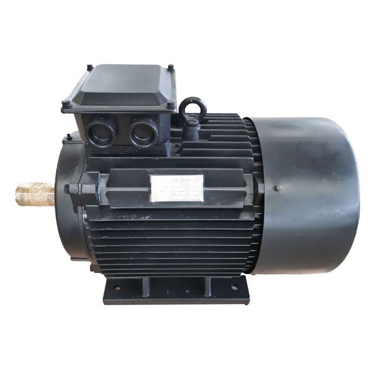
Engineering Consultation and Drive Upgrade Inquiries
Determining the precise operational savings of a Permanent Magnet Synchronous Motor upgrade begins with a detailed assessment of facility load profiles, feeder impedance, and utility billing structures. Transitioning production assets to permanent magnet motor systems mitigates harmonic stress, lowers apparent current demand, and elevates overall facility energy efficiency. Application specialists provide comprehensive electrical system modeling, shaft interface engineering, and turnkey drive selection support. Contact the engineering team today to review specific plant parameters and project requirements.
- WhatsApp: +86 18562780228
- E-Mail: [email protected]
- Phone: +86 532 66000559
FAQ
Q: Why does a permanent magnet synchronous motor maintain a higher power factor than an induction motor?
A: A Permanent Magnet Synchronous Motor utilizes rare-earth rotor magnets to generate the primary magnetic field, eliminating the need to draw reactive magnetizing current from the power grid. Stator current remains predominantly in phase with terminal voltage, allowing the machine to achieve power-factor levels above 0.96. Induction motors must continuously consume reactive current to energize their rotor conductors, inherently lowering operational power factor.
Q: How does improved motor power factor reduce utility operational expenditures?
A: Industrial electric utility providers routinely penalize facilities that operate below specific power-factor thresholds, typically 0.90 or 0.95, by charging reactive power penalties and increased demand fees. Upgrading to a PM Synchronous Motor raises facility power-factor performance naturally at the equipment level. This reduction in apparent power eliminates utility penalties, minimizes line losses, and lowers total monthly kilowatt-hour consumption.

