In heavy-duty rubber internal mixers, mineral ball mills, twin-screw plastic extruders, and low-speed mine hoists, machinery shafts require massive breakaway and continuous rotational torque at speeds ranging from 10 RPM to 300 RPM. When equipment builders attempt to power these high-torque, low-speed loads using conventional four-pole or six-pole asynchronous induction motors, they are forced to rely on bulky multi-stage reduction gearboxes, fluid couplings, or oversized motor frames. Under severe starting loads and continuous low-RPM operation, traditional asynchronous drivetrains suffer from high rotor slip heat, poor power factor, gearbox tooth fatigue, and frequent thermal overload trips.
The fundamental limitation of an asynchronous induction motor in low-speed, high-torque service lies in its electromagnetic physics: generating high torque requires inducing large electrical currents in the rotor cage, and building a high-pole-count induction motor causes magnetizing current losses to skyrocket while the power factor plummets below 0.65. Transitioning to a purpose-engineered Permanent Magnet Synchronous Motor from ENNENG overcomes these electromagnetic barriers, delivering exceptional torque density and cool, zero-slip rotation directly at low industrial speeds.
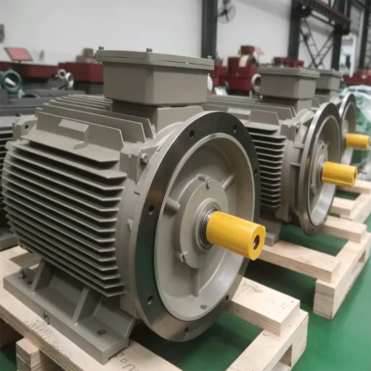
Technical Highlights: Why Asynchronous Physics Struggles at Low Speed and High Torque
Magnetizing Flux Leakage and Severe Power Factor Collapse in Multi-Pole Induction Motors
To make a conventional AC induction motor spin natively at low RPM without a massive gearbox, engineers must increase the number of stator magnetic poles (for example, to 12, 16, or 24 poles). However, as pole pitch narrows in a multi-pole induction motor, magnetic flux leakage across the air gap increases dramatically. The stator winding must draw enormous reactive magnetizing current just to excite the rotor core, causing the motor's power factor to collapse to 0.55–0.70 and forcing the motor frame to become physically enormous and thermally inefficient.
Multi-Pole Rare-Earth Excitation of the Permanent Magnet Synchronous Motor
An ENNENG Permanent Magnet Synchronous Motor is fundamentally suited for low-speed, high-torque industrial duty because its rotor magnetic field is supplied by high-energy permanent magnets rather than stator-induced current:
-
High Pole-Count Design Without Power Factor Penalty: Because permanent magnets establish air-gap flux independently of stator magnetizing current, an ENNENG Permanent Magnet Synchronous Motor can be built with 16 to 60+ poles while maintaining a near-unity power factor (0.95 to 1.00).
-
Zero Rotor Copper Loss Under Stall and Breakaway Torque: Delivering 150% to 200% starting breakaway torque on a loaded conveyor or mixer generates zero resistive heat inside the rotor, preventing thermal demagnetization or rotor bar cracking.
-
Superior Torque-to-Weight and Frame Density: Concentrating high magnetic flux density across the rotor periphery produces 30% to 50% higher continuous torque per unit of frame volume compared to asynchronous equivalents.
Core Advantages of ENNENG Permanent Magnet Synchronous Motor Systems
Gearless Direct Torque Delivery Across 110V–690V Industrial Supplies
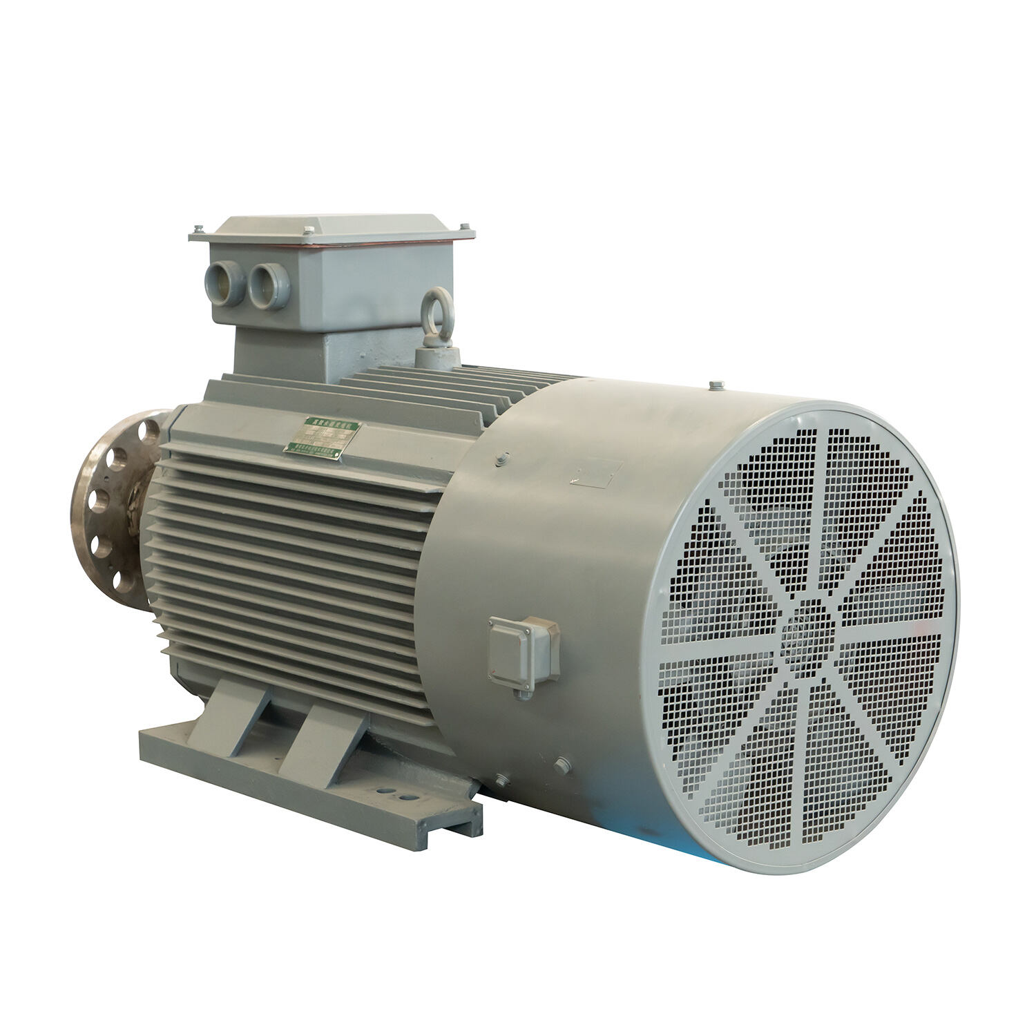
By generating massive tangential force natively at low rotational speeds, an ENNENG Permanent Magnet Synchronous Motor couples directly to low-speed industrial rolls, drums, and agitator shafts—eliminating multi-stage reduction gearboxes, V-belts, and hydraulic couplings. Engineered across a unified voltage range of 110V–690V, these synchronous drive systems eliminate 8% to 15% in mechanical reducer friction losses while reducing line current draw on factory transformers. Beyond heavy industrial propulsion drives, ENNENG applies this multi-pole low-speed physics to permanent magnet generators spanning a unified 5kW–5MW power range (110V–690V) and vertical axis wind turbines from 1kW–10kW, with a main focus on 3kW, 5kW, and 10kW renewable generation units.
Complying with IEC TS 60034-30-2, IEC 60034-1, and ISO 10816 Standards
Heavy-duty low-speed industrial drives must satisfy strict thermal, overload, and mechanical vibration codes. Every ENNENG Permanent Magnet Synchronous Motor is engineered and tested in compliance with IEC 60034-1 for continuous S1 duty and short-time overload torque capability, while achieving IE5 ultra-premium efficiency under IEC TS 60034-30-2 across variable speed-torque points. Furthermore, eliminating gear-mesh backlash and asynchronous slip pulsations keeps bearing housing vibration well within ISO 10816-3 Class I limits, protecting driven machinery shafts and seals from fatigue failure.
Industrial Application Scenarios and Engineering Maintenance Guide
1. Rubber Banbury Mixers, Extruders, and Slurry Thickener Drives
In tire compounding mixers and mineral slurry thickeners, viscosity spikes subject the drive shaft to severe low-RPM torque shocks. Installing an ENNENG Permanent Magnet Synchronous Motor provides instantaneous closed-loop vector torque response without rotor slip stall or gearbox tooth stripping.
2. Practical Selection, Inspection, and Maintenance Protocols
To ensure optimal performance and multi-decade reliability when applying a Permanent Magnet Synchronous Motor to low-speed, high-torque machinery, follow these engineering guidelines:
-
Specify Continuous Rated Torque (Nm) Rather Than Kilowatts Alone: At low rotational speeds, mechanical power (kW) is modest even when shaft torque (Nm) is massive; always size the Permanent Magnet Synchronous Motor based on continuous running torque and peak breakaway torque requirements.
-
Select Forced Ventilation (IC416) or Water Cooling (IC71W) for Ultra-Low RPM: When a high-torque motor operates continuously below 150 RPM, specify an independent blower fan (IC416) or water-cooled stator jacket (IC71W) to guarantee constant heat dissipation independent of shaft speed.
-
Configure VFD Low-Speed Rotor Position Tracking: Utilize an absolute rotary encoder, resolver, or high-frequency injection sensorless vector algorithm on the VFD to maintain precise 100%+ holding and starting torque from zero RPM.
-
Verify Torsional Coupling and Baseplate Bolt Preload: Inspect high-torque shrink discs or rigid flange couplings during scheduled turnarounds to confirm zero micro-fretting under heavy cyclic torque reversals.
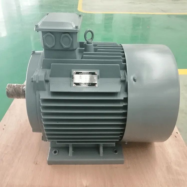
The ENNENG Customisation Advantage
Low-speed, high-torque industrial machines rarely conform to standard catalog motor dimensions. ENNENG custom-engineers its Permanent Magnet Synchronous Motor series across the unified 110V–690V range—tailoring rotor pole counts for exact rated speeds from 10 RPM to 600 RPM, hollow-shaft or flange-mount geometries, and IC416/IC71W cooling packages to integrate directly into heavy OEM machinery.
Contact ENNENG Today.
Consult the ENNENG high-torque drive engineering team to evaluate your low-speed torque curves and receive a customised Permanent Magnet Synchronous Motor proposal.
FAQ
Q: Why does a multi-pole Permanent Magnet Synchronous Motor maintain a high power factor at low speeds where induction motors fail?
A: When an induction motor is designed with many poles for low-speed operation, air-gap flux leakage increases and the stator must draw huge reactive current to magnetize the rotor, dropping power factor below 0.65. An ENNENG Permanent Magnet Synchronous Motor uses rotor permanent magnets for excitation, maintaining a 0.95 to 1.00 power factor even at ultra-low RPM.
Q: How does an ENNENG Permanent Magnet Synchronous Motor handle continuous full-torque operation at very low RPM without overheating?
A: In a conventional induction motor, delivering high torque at low speed induces heavy rotor currents that rapidly overheat the rotor cage. Because an ENNENG Permanent Magnet Synchronous Motor generates zero rotor copper loss and can be equipped with IC416 forced-air or IC71W water-jacket cooling, it delivers continuous full rated torque down to single-digit RPM safely.
Q: What voltage and power generation ranges does ENNENG manufacture using synchronous permanent magnet technology?
A: ENNENG manufactures its Permanent Magnet Synchronous Motor portfolio across a unified voltage range of 110V–690V for global industrial compatibility. Applying the same low-speed high-torque electromagnetic design to power generation, ENNENG supplies permanent magnet generators across a unified 5kW–5MW power range and vertical axis wind turbines from 1kW–10kW (focusing on 3kW, 5kW, and 10kW models).

 EN


