
why-permanent-magnet-synchronous-motor-is-widely-adopted-in-energyintensive-industrial-upgrading-projects, why-permanent-magnet-synchronous-motor-is-widely-adopted-in-energyintensive-industrial-upgrading-projects, /blog
EN

2026/10/10
Continuous manufacturing sectors such as metallurgy, chemical synthesis, and paper production operate heavy equipment around the clock where electrical machinery consumes more than 70% of total plant energy. Facility management teams executing modernization projects face strict regulatory mandates to lower specific energy consumption per ton of product while maintaining process stability. Under these intense operating demands, conventional induction drives waste substantial amounts of electrical energy through continuous rotor slip and low operating power factors. Deploying a modern Permanent Magnet Synchronous Motor replaces inefficient legacy drivetrains with high-density electromechanical architecture, enabling direct electrical energy reductions across continuous-duty production lines.
Processing facilities operate grinding mills, heavy conveyor lines, and large gas-scrubbing blowers under uninterrupted S1 operating duty between 6,500 and 8,400 hours per calendar year. Under such sustained duty cycles, the total lifetime cost of an electric motor is dominated by electricity bills, which frequently represent more than 92% of total life-cycle expenditures. When facilities operate aging squirrel-cage induction drives, stator windings must continuously supply magnetizing current to induce rotor flux across the air gap. This constant magnetizing draw causes severe resistive rotor heating and high stator copper losses that persist throughout every production shift.
Running fleets of standard asynchronous motors under shifting industrial loads introduces serious secondary vulnerabilities to plant infrastructure. When production throughput drops, induction motor power factors degrade sharply, often dropping from 0.85 at nominal load down to 0.55 at fractional loads. Plant transformers and switchgear must absorb this reactive current burden, triggering voltage drops, accelerated transformer heating, and recurring utility penalties. Internally, continuous rotor slip losses generate excessive internal rotor heat that radiates into bearing journals, causing bearing grease oxidation, seal failure, and insulation breakdown. To eliminate these chronic threats, ENNENG supplies advanced industrial Permanent Magnet Synchronous Motor systems engineered across the 5kW to 5MW power spectrum and 110V to 690V operating ranges.
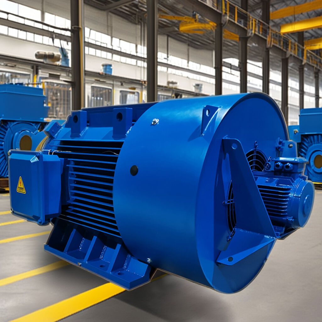
The foundational advantage of a Permanent Magnet Synchronous Motor stems from its rotor design. Rather than relying on induced electromagnetic currents, the motor establishes permanent magnetic air-gap flux using high-coercivity rare-earth neodymium-iron-boron magnets embedded within the rotor core. Because magnetic excitation is continuous and self-sustaining, the motor draws zero magnetizing current from the AC supply. Synchronous operation ensures that the rotor turns in precise synchronization with the stator rotating magnetic field, eliminating rotor slip entirely. Without slip current, rotor resistive I²R heat generation is eliminated, allowing an ENNENG Permanent Magnet Synchronous Motor to maintain IE5 ultra-premium efficiency levels even when process equipment throttles back to 30% load.
In contrast to conventional induction drivetrains that experience steep efficiency drop-offs outside their narrow sweet spot, a Permanent Magnet Synchronous Motor delivers a remarkably flat efficiency profile across 25% to 100% of rated output. Driven by advanced variable-speed frequency converters running field-oriented vector control, the drive system maintains an operating power factor exceeding 0.95 across wide operational envelopes. Facility electrical infrastructure benefits immediately from reduced kVA apparent power draw, decreased harmonic heating in distribution transformers, and lower ventilation cooling burdens inside electrical equipment substations.
|
Operational Metric |
Aging Induction Motor (IE2) |
Standard Induction Motor (IE3) |
ENNENG PMSM (IE5) |
|
Full Load Efficiency (250kW Rating) |
94.0% |
95.8% |
97.4% (Ultra-Premium Class) |
|
50% Load Efficiency Benchmark |
89.2% |
91.5% |
96.8% (Sustained High Efficiency) |
|
Operating Power Factor (Full Load) |
0.85 |
0.87 |
0.97 - 0.99 (Unity Approximation) |
|
Power Factor at 30% Partial Load |
0.52 |
0.61 |
0.93 (Zero Reactive Burden) |
|
Rotor Heat Dissipation Rate |
High (Continuous Slip Current) |
Moderate (Induced Core Losses) |
Negligible (Cold Rotor Architecture) |
|
Continuous Power Range Spectrum |
Catalog Standard Frames |
Catalog Standard Frames |
5kW to 5MW Unified Platform |
|
Operating Drive Voltage Range |
Fixed Industrial Voltages |
Fixed Industrial Voltages |
110V to 690V Variable Control |
Large-scale motor retrofits in energy-intensive facilities require rigorous alignment with international industrial efficiency protocols. International standard IEC 60034-30-2 defines testing methodologies and efficiency tiers for variable-speed AC motors, establishing IE5 criteria that ENNENG drivetrains surpass across dynamic speed envelopes. Modernization projects aimed at certified sustainability utilize the Permanent Magnet Synchronous Motor as an auditable technical measure to fulfill ISO 50001 Energy Management Systems benchmarks. Electrical installation complies strictly with NFPA 70 Article 430 requirements, ensuring correctly dimensioned disconnect switches, thermal overload coordination, and branch circuit conductor protection.
Step-by-Step Retrofit Engineering and Maintenance Procedures:
Conduct Fleet Energy Census: Measure active kW draw, operating hours, and load profiles across continuous S1 drives to calculate precise payback periods.
Verify Drop-In Mechanical Interchangeability: Select ENNENG permanent magnet units designed with standardized IEC and NEMA foot-mounting dimensions and shaft heights to avoid structural modifications.
Calibrate Inverter Motor Modeling: Input motor back-EMF constants, direct-axis inductance (Ld), and quadrature-axis inductance (Lq) into the drive parameter library for optimal vector control.
Implement Predictive Monitoring: Monitor stator PT100 temperature sensors and establish vibration baselines per ISO 10816 standards to maximize bearing grease service life.
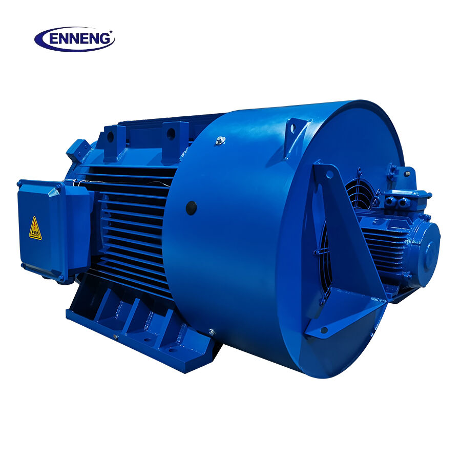
Transitioning high-consumption manufacturing lines to ultra-premium permanent magnet efficiency requires proven motor engineering and matched variable-speed automation. The application specialists at ENNENG assist heavy industrial facilities in completing electrical load surveys, return-on-investment calculations, and turnkey motor retrofit integration. Submit facility operating requirements to schedule a comprehensive industrial upgrade consultation:
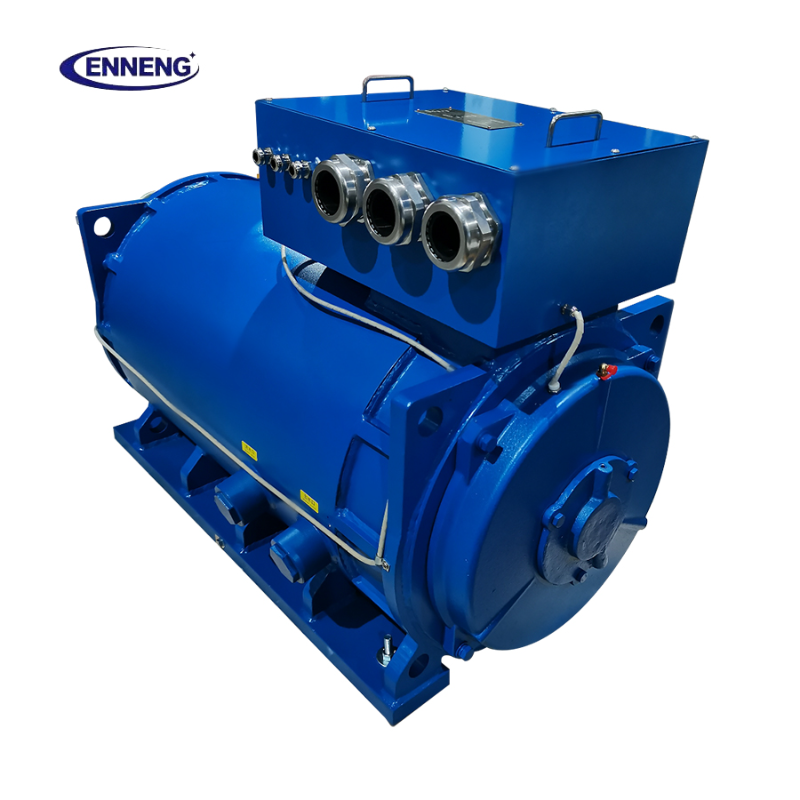
A: A Permanent Magnet Synchronous Motor maintains high partial-load efficiency because its excitation field is generated by permanent magnets rather than stator-induced current. Without rotor copper losses, the primary energy expenditure scales directly with the mechanical torque demanded by the driven machine. Consequently, core losses and thermal dissipation remain minimal, allowing the motor to sustain IE5 efficiency levels even during severely throttled light-load operation.
A: A Permanent Magnet Synchronous Motor cannot connect directly across standard line power; it requires an inverter equipped with field-oriented vector control. The variable frequency drive monitors rotor position via encoder feedback or sensorless high-frequency injection algorithms to synchronize output current with the permanent magnet field, ensuring smooth torque generation, accurate speed regulation, and maximum efficiency across wide partial-load operating ranges.
Q: How does thermal management differ between induction motors and a Permanent Magnet Synchronous Motor?
A: In standard induction machinery, rotor resistance creates significant internal heat that passes through bearings and shafts. In a Permanent Magnet Synchronous Motor, the rotor remains cool because no slip currents exist, reducing thermal stress on mechanical bearings. Heat is concentrated almost entirely in the stator housing, where external cooling fins and forced ventilation dissipate thermal energy efficiently during continuous industrial service.


 EN