
 EN

A factory can have adequate transformer capacity and still experience overloaded feeders, elevated cable heating, or poor power-factor readings. The cause is often not a shortage of useful kW but the current needed to establish magnetic fields. A PM Synchronous Motor can reduce one important source of that current because its rotor field comes from permanent magnets rather than rotor excitation drawn from the AC supply. That distinction can lower the motor’s magnetizing reactive-power demand and, in the right duty cycle, reduce current-related loss upstream.
The important qualifier is “in the right duty cycle.” A motor replacement is not a universal power-factor correction project. Variable-speed drives, harmonics, lightly loaded equipment, cable length, transformer loading, and the existing capacitor bank can all affect what the plant meter shows. The useful question is therefore not simply whether a Permanent Magnet Motor PMSM is efficient; it is whether it reduces the kVAr and current that are actually circulating through a particular feeder.
Reactive power is a distribution-current problem, not just a utility-bill number
In an AC motor system, real power (kW) produces shaft work, while reactive power (kVAr) supports magnetic fields. Together they determine apparent power (kVA). For a given mechanical load, a lower power factor means more current must pass through switchgear, cables, transformers, and protection devices. Since conductor heating loss rises with the square of current, even a modest current reduction can relieve losses and thermal stress along a heavily loaded path.
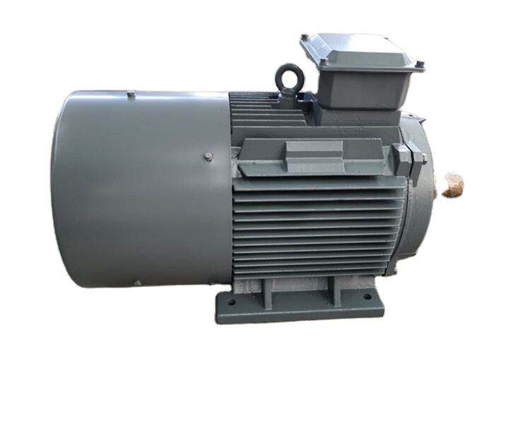
Induction motors need magnetizing current to establish air-gap flux. That current is largely reactive and is especially noticeable when the machine runs well below its rated load. A PM Synchronous Motor carries permanent magnets on the rotor, so the rotor field does not need to be created in the same way from stator-supplied magnetizing current. The stator still carries controlled current, and its reactive component depends on the drive, control mode, speed, torque, and machine design. But the motor can be operated closer to unity fundamental power factor than a comparable induction motor in many applications.
Where a PM Synchronous Motor changes the electrical picture
The key mechanism is field excitation. In a conventional induction machine, the stator supplies both torque-producing current and magnetizing current. In a Permanent Magnet Motor PMSM, the rotor magnets provide the rotor flux. A vector-controlled drive can then regulate the d-axis and q-axis current components to produce the required torque while avoiding unnecessary reactive current within the operating limits of the motor and inverter.
That can produce three related gains inside factory distribution:
- Lower feeder current for the same shaft task: when kW demand is unchanged but the reactive component falls, kVA and current can fall too.
- Lower I²R losses: less RMS current through cables, busways, transformer windings, and contact resistance means lower current-dependent loss.
- More usable distribution capacity: reduced kVA demand may create margin for other loads without increasing transformer or feeder size.
None of these effects should be assumed from a nameplate alone. A high efficiency class and a favorable motor power factor are useful indicators, but they do not substitute for measurements at the actual load profile.
Why partial-load factories often see the largest opportunity
Many pumps, fans, compressors, conveyors, and process auxiliaries do not stay at rated load. A production line may idle between batches; an air-handling unit may follow a temperature loop; a pump may be throttled or slowed. This is where comparing only full-load efficiency can hide the distribution effect.
A useful specification shift is to ask whether the duty cycle actually reaches the point where peak efficiency is quoted. For equipment that spends long periods at partial load, examine the efficiency map, input current, and fundamental power factor over the operating range—not only the rated point. If the load is steady and near full load, the incremental reactive-power advantage may be smaller; if the load varies widely, the combined control and motor behavior can be more consequential.
Do not confuse motor improvement with capacitor-bank correction
Capacitor banks compensate inductive kVAr at a bus or feeder. A PM Synchronous Motor reduces or changes the reactive demand at the load itself. These approaches can complement each other, but they are not interchangeable.
|
Question |
PM motor and drive approach |
Capacitor-bank approach |
|
Where is reactive demand addressed? |
At the motor/load operating point |
At a distribution bus or feeder |
|
What else can change? |
Motor efficiency, speed control, and part-load behavior |
Primarily system-level displacement power factor |
|
What must be checked? |
Drive harmonics, control settings, duty cycle, motor limits |
Switching steps, resonance risk, load variation |
|
Can it eliminate all kVAr work? |
No; other inductive loads remain |
No; it does not improve the motor’s conversion losses |
It is tempting to treat a PM machine as a replacement for a capacitor bank. In practice, a factory also contains transformers, other motors, welding equipment, and drives with their own power-quality behavior. Any capacitor-bank changes should follow a coordinated power-quality study, particularly where variable-frequency drives are common.
A practical verification plan for a factory feeder
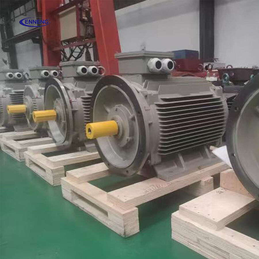
Start with a baseline rather than a catalogue comparison. Meter the feeder that supplies the target equipment across representative production states: idle, typical load, peak load, and any frequent speed points. Record kW, kVAr, kVA, RMS current, voltage, fundamental power factor, total power factor, and current THD. If a plant uses demand charges or contractual power-factor limits, record the billing interval data as well.
- Map the load profile. Identify how many hours occur at each speed and torque range; a single spot reading is rarely enough.
- Confirm the system boundary. Decide whether the comparison is measured at the motor terminals, VFD input, local panel, or main distribution board.
- Compare like-for-like output. Verify shaft speed, process throughput, pressure, flow, or conveyed mass so that lower current is not merely lower production.
- Check drive-side power quality. Review input reactors, filters, DC bus behavior, and harmonic limits alongside fundamental kVAr.
- Reassess capacitor steps. After the new operating data is stable, determine whether existing compensation steps are still appropriate.
Specification details that decide whether the benefit is real
Ask suppliers for efficiency and current data across the intended speed-torque envelope, not just the rated point. Confirm the inverter compatibility, allowable switching frequency, cooling method, insulation system, cable length constraints, and protection settings. IEC efficiency classifications provide useful context for comparison, but compliance claims should be verified against the exact motor and applicable standard scope.
PM Synchronous Motor commissioning checklist
Use this compact checklist to keep the comparison tied to plant evidence rather than nameplate assumptions:
- PM Synchronous Motor: log kW, kVAr, kVA, current, and production rate at the VFD input.
- Permanent Magnet Motor PMSM: compare matched speed/torque points, fundamental and total PF, current THD, cable temperature, and the feeder boundary.
- PM Synchronous Motor: verify drive settings, filters, capacitor-bank response, comparable demand intervals, and acceptance readings.
Credit a PM Synchronous Motor only when its electrical and production boundaries are comparable.
When the case is strongest—and when it is not
A PM Synchronous Motor is most worth investigating where a large population of induction motors runs for long hours, where loads frequently operate below rated point, where feeder current or transformer loading is constrained, and where variable-speed control is already needed. Fans, pumps, compressors, and continuous material-handling equipment are common candidates, provided the process and drive architecture fit.
The case is weaker when the existing motor already operates close to an optimal point, the run time is low, the distribution loss path is short, or power-quality issues from the VFD have not been engineered. The technology is not a shortcut around undersized cables, poor voltage balance, or uncontrolled harmonics.
The ENNENG Customisation Advantage
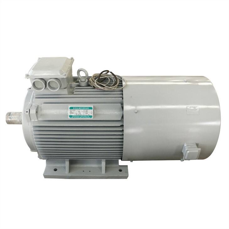
No two industrial facilities share the same spatial or mechanical constraints. ENNENG stands out because we do not just supply off-the-shelf catalogue products; we specialise in delivering a tailor-made permanent magnet motor tailored to your specific application .
Supported by our elite R&D team consisting of engineers from the National Rare Earth Permanent Magnet Engineering Centre, and backed by dozens of patents, we customise high-voltage (6kV/10kV) and low-voltage (380V/660V/1140V) solutions to match your existing footprint. From water treatment facilities and oil wells to explosion-proof mining environments, we deliver optimal performance where general-purpose motors fail .
If you are evaluating commercial permanent magnet motors for sale and need an engineered drive solution that guarantees efficiency and longevity, ENNENG is your trusted partner.Contact ENNENG Today.Speak to our technical engineering team to receive a customised drive proposal.
- WhatsApp: +86 18562780228
- E-Mail: [email protected]
- Phone: +86 532 66000559

