
why-pm-synchronous-motor-delivers-stable-torque-output-under-complex-variablespeed-working-modes, why-pm-synchronous-motor-delivers-stable-torque-output-under-complex-variablespeed-working-modes, /blog
EN

2026/09/15
Machines that ramp, hold, and reverse put a torque demand on the drive that a fixed-speed rating never reveals. A PM Synchronous Motor is built to meet it, because the rotor field is locked to the supply and torque stays available from standstill to rated speed. The hard part is keeping that torque steady through rapid reversals and long low-speed holds without the unit slipping out of step or running hot. The PM Synchronous Motor makes that profile routine instead of risky.
One processing line ran an extruder that needed full torque at a slow metering speed before a fast screw run. The previous drive lost authority at the slow hold and stalled the melt, forcing an over-rated replacement that wasted energy all day. After a PM Synchronous Motor replaced it, the metering hold kept its torque and the fast run stayed efficient. The PM Synchronous Motor removed the two-speed compromise, because torque was present wherever the screw demanded it on the curve.
A drive that only works near rated speed fails the moment the duty drops to a hold or a creep. A PM Synchronous Motor is stressed by exactly those points, where weaker designs lose field or control and let the shaft drift. A reversal adds a sudden torque step that loads the rotor and coupling, while a long hold builds heat if the cooling assumes full speed. The PM Synchronous Motor must stay locked and stable through all of it, which is a different requirement from a single point on a clean curve. Most lines change their mode mix weekly, so the drive lives in transition more than at any one speed.
The machine keeps torque by holding the angle between rotor and stator fields, and by letting control track the setpoint. A PM Synchronous Motor earns its name through that lock, not through a larger frame.
Torque in a synchronous machine is set by the angle between the rotor magnet field and the stator field, and the unit stays stable as long as that angle stays below pull-out. A PM Synchronous Motor sized with pull-out torque well above the peak demand cannot slip out of step during a ramp or a jam. Because the magnet fixes the field, the available torque does not fade at low speed the way an induction design does, so the PM Synchronous Motor gives the same authority from rest to rated speed.
The drive aligns stator current to the rotor position, so the PM Synchronous Motor delivers torque without hunting or slip. At a reversal the controller manages the step and keeps the angle inside its limit, and at a hold it trims current to avoid pointless heating. The PM Synchronous Motor therefore stays stable because the magnet supplies the torque while the control supplies the discipline, and together they suit the variable-speed work that modern lines demand.
A converter-fed synchronous machine lives or dies by how the motor, drive, and cable are qualified together, not by a standalone nameplate. The right standards turn the torque and stability claim into checkable numbers a plant can audit.
IEC 60034-25 gives the rules for a.c. motors built to run from a converter instead of direct mains, covering the voltage shapes, switching, and thermal effects a PM Synchronous Motor meets in real service. Specifying to it prevents the classic failure where a fine motor is wrecked by a drive it was never qualified against, so the PM Synchronous Motor keeps its insulation and balance under genuine pulse duty.
IEC 61800-7 sets the control and interface profiles for adjustable-speed drives, the layer where load-angle control and the converter actually talk. A PM Synchronous Motor performs only as well as that handshake allows, because position feedback and the torque command must match the profile. Following the standard lets a plant swap or tune drives without re-deriving the whole control loop the motor depends on.
Specifying and running the unit starts from the mode profile, not from one rated point. A PM Synchronous Motor stays in step only when the converter, feedback, and commissioning are set to the duty it actually runs.
List the peak load angle and the pull-out reserve before quoting, because that margin — not the nameplate speed — decides whether the PM Synchronous Motor stays locked. Ask for the position-feedback resolution the field-oriented controller needs, the switching frequency the insulation is qualified for under IEC 60034-25, and the control mode the process demands. A converter matched to those limits means the line gains stability from the first day instead of after a costly over-sizing.
Watch the items a converter drive ages first: encoder alignment, bus-capacitor health, and the insulation partial-discharge trend the switching creates. A PM Synchronous Motor should be checked for synchronization drift during a real ramp and reversal, not only at idle, because a slow loss of lock shows up as current ripple before it shows as heat. Keep the converter parameters and the feedback commissioning record filed, because the PM Synchronous Motor relies on that tuning to stay in step as the profile shifts.
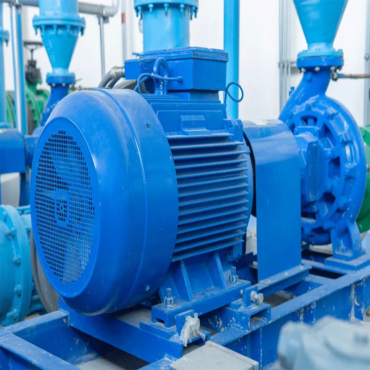
The rotor magnet sets the field, so torque does not depend on the stator building flux as speed falls. A PM Synchronous Motor therefore holds strong torque during a slow hold or creep, where the process often needs it most. Because the field is present from standstill, the response is steady across every mode change, and the torque curve stays flat enough to trust through ramps without sagging or stalling the load.
Pull-out torque is the maximum load angle the machine can hold before it slips out of step. A PM Synchronous Motor sized with comfortable pull-out margin stays locked during a ramp, a jam, or a reversal instead of losing sync. That margin is what separates a stable variable-speed drive from one that drops out under a hard step, and it should be checked against the peak demand, not the average.
The drive measures rotor position and aligns the current to it, so the PM Synchronous Motor produces torque without slip or hunting. During a reversal the controller keeps the load angle inside its limit, and during a hold it reduces current to avoid waste heat. The magnet supplies the torque while the control supplies the precision, and the two together hold the output steady across the speed range.
Yes, because the field is fixed and the controller manages the torque step. A PM Synchronous Motor can take a rapid direction change and stay locked as long as the load angle stays within pull-out. Closed-loop control prevents slip during the swing, which is the failure that defeats drives built around a single steady speed. That is why the same unit serves both forward and reverse duty cleanly.
IEC 60034-25 covers a.c. motors built for converter supply, including the switching and thermal effects a PM Synchronous Motor meets in service. IEC 61800-7 sets the control and interface profiles where the load-angle loop actually runs. A PM Synchronous Motor is best judged on that combined basis, because the mode changes move stress between the motor, the converter, and the cable across the operating day.
Inspect against the duty, not only the calendar. A PM Synchronous Motor deserves a thermal scan during a real ramp and reversal and a monthly log of current and temperature. Watch bearing heat, encoder signal, and cooling cleanliness, because variable stress ages them first. A rising trend predicts failure, and the profile shifts often enough that recorded tuning protects the lock and the stability the motor was chosen for.


 EN