
 EN

Why PM Synchronous Motor Helps Factories Improve Internal Power-Grid Quality
Factory power quality is often discussed after a nuisance trip, an overheated transformer, or a production line that behaves differently when several large drives start together. Yet the issue begins earlier: at the point where a motor, its load, its control method, and the plant distribution system meet. A PM Synchronous Motor can help improve this picture, particularly in variable-speed pump, fan, compressor, and process-drive duties. The important qualifier is that the benefit comes from a correctly engineered motor-and-drive system, not from a motor nameplate alone.
From a procurement standpoint, a power-system upgrade should be judged by lifecycle operating behavior as well as purchase cost. A lower-loss drive train can reduce current demand for the same mechanical work; careful converter selection and commissioning can also avoid adding unnecessary distortion to the internal network. In practice, the useful question is: which measurements will show whether the PM Synchronous Motor installation is helping this specific factory?
Power quality inside a factory is more than the utility bill
Internal power quality describes how reliably and cleanly electrical energy is delivered to loads within the site. Engineers commonly watch voltage variation, voltage unbalance, power factor, current harmonics, voltage harmonics, inrush, flicker, and thermal loading of cables and transformers. These variables interact. A process line may have sufficient installed kW capacity and still suffer from voltage dips during starts, distorted current from poorly configured drives, or uneven phase loading that shortens equipment life.
That is why a PM Synchronous Motor should be evaluated as part of a system. The motor itself has a permanent-magnet rotor and is normally paired with an appropriately matched variable-frequency drive (VFD). The VFD shapes the voltage and current supplied to the motor; upstream reactors, filters, cable length, transformer impedance, switching frequency, grounding, and control tuning also affect the result seen by the plant bus.
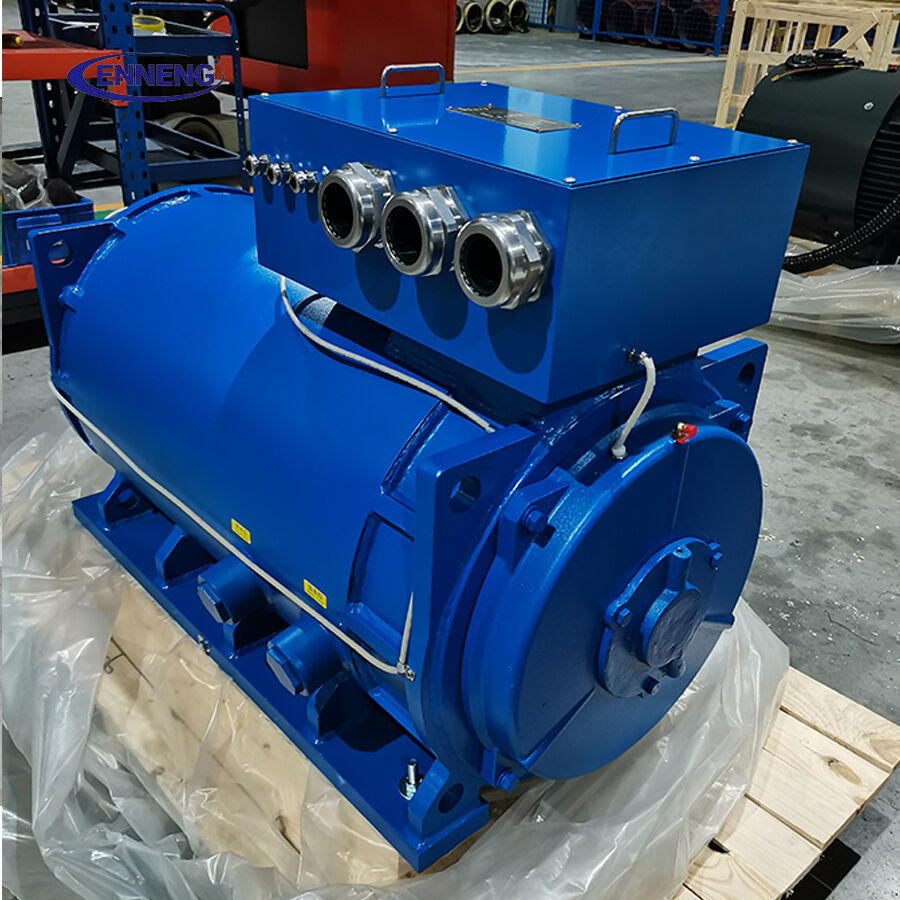
How a PM Synchronous Motor can reduce electrical stress
Lower losses can reduce current for the required shaft work
Compared with a less efficient alternative under the same operating conditions, a PM Synchronous Motor can require less input power to deliver the needed shaft output. That does not automatically cure harmonic distortion, but it can lower steady-state feeder current, I²R cable losses, transformer heating, and voltage drop. The effect matters most when a process spends long periods at part load rather than running continuously at one nameplate point.
One distinction matters here: high efficiency is not the same as high power quality. Efficiency reduces avoidable real-power losses; power quality must still be measured at the relevant bus or point of common coupling. IEC TS 60034-30-2 provides an efficiency-class framework for variable-speed AC motors, while the site design must separately address converter behavior and network conditions.
Controlled starting avoids across-the-line inrush
A VFD-operated PM Synchronous Motor accelerates with managed frequency and torque rather than an abrupt across-the-line connection. For a pump or fan, that can substantially reduce the starting-current event that otherwise depresses a weak internal bus and disturbs nearby controls. The actual ramp must still be matched to the driven equipment: a ramp that is too fast can demand excessive torque, while an unnecessarily slow one may conflict with process requirements.
Think of a water-transfer pump supplied from a transformer that also feeds instrumentation and packaging equipment. The aim is not merely to make the pump start. It is to start it without provoking a voltage dip that resets sensitive devices or forces operators to sequence unrelated loads by hand.
Speed control can prevent avoidable cycling and peak demand
Where flow or air demand varies, throttling valves, dampers, and repeated fixed-speed starts can create inefficient operating patterns. A PM Synchronous Motor with a suitable drive can follow a demand signal more smoothly. Less abrupt load change can make the internal demand profile easier to manage and may reduce mechanical shocks as well. The result depends on the load curve, process controls, and minimum safe speed; it is not a universal promise for every application.
The drive is critical to harmonic performance
You might be thinking: if the PM motor is efficient, the power-quality work is complete. The problem with that approach is that the VFD is a nonlinear load, and its input stage can introduce harmonic current. If the plant impedance converts that current into voltage distortion, other equipment may be affected. A good PM Synchronous Motor project therefore includes the drive topology and mitigation plan from the first electrical single-line review.
- Confirm transformer capacity, available fault level, feeder impedance, cable routing, and existing nonlinear loads.
- Select the VFD input arrangement for the site, considering line reactors, DC chokes, passive or active harmonic filters, or other appropriate mitigation.
- Review motor-cable length, insulation coordination, grounding, and any required output filtering to manage reflected-wave and bearing-current risks.
- Set acceleration, deceleration, torque limits, and switching parameters during commissioning rather than relying on factory defaults.
- Measure before and after installation under representative production conditions.
IEEE 519 is commonly used as a reference for harmonic control at a point of common coupling, but applicable targets depend on voltage class and the system’s short-circuit and load conditions. It should guide an engineering assessment, not be used as a generic compliance label for a motor package.
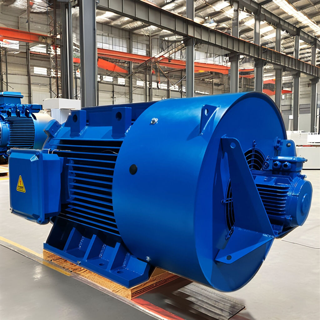
A practical factory upgrade walkthrough
Consider a generalized process area with variable-load fans, periodic voltage dips during starts, and a transformer already supplying several VFDs. The first step is a baseline survey. Record kW, kVA, power factor, current and voltage THD, demand peaks, phase balance, bus voltage, and key event logs over representative shifts. A one-hour snapshot is rarely enough if load patterns change across batches.
Next, define the mechanical duty: speed range, required breakaway torque, inertia, load profile, ambient temperature, enclosure, and maintenance access. Treating a PM Synchronous Motor power rating as a fixed number is fine for rough planning; once ambient conditions, overload duty, and the actual speed range enter the calculation, the usable continuous range can shift considerably.
Then specify the motor, VFD, and upstream mitigation as one package. Qingdao Enneng Motor Co., Ltd. designs and manufactures permanent-magnet motors and generators with in-house winding capability, which can support application-specific discussions of winding, frame, and duty requirements. A final selection still requires the customer’s electrical and mechanical data, and any site-specific claims should be confirmed during design review.
At commissioning, compare the same operating point before and after the change. Check whether starting-related voltage events are reduced, whether current demand and temperature margins are improved, and whether harmonic values remain acceptable at the selected measurement point. If results are not as expected, look first at drive settings, filter installation, network resonance, grounding, and the interaction with other nonlinear loads—not at the motor alone.
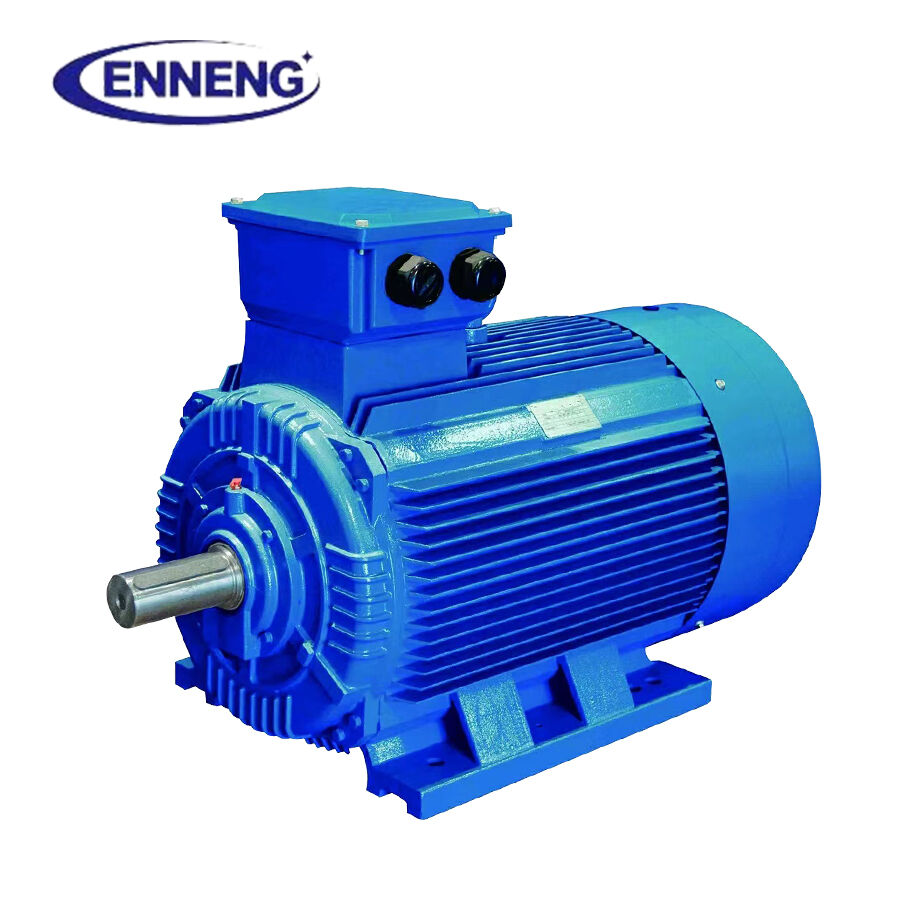
What to include in a PM Synchronous Motor specification
| Decision area | Information to provide | Why it affects internal power quality |
|---|---|---|
| Mechanical duty | Load curve, speed range, starts per hour, inertia, required torque | Supports accurate motor and ramp selection. |
| Electrical network | Voltage, frequency, transformer data, feeder length, existing VFD load | Reveals voltage-drop and harmonic-interaction risks. |
| Drive architecture | Input reactor or choke, filter approach, switching constraints, EMC needs | Determines much of the input-current and emission behavior. |
| Acceptance testing | Baseline metrics, measurement point, load condition, pass criteria | Turns expected benefits into verifiable site results. |
Make power quality a measured outcome
A PM Synchronous Motor can contribute to a cleaner, more stable internal supply by lowering losses, moderating starts, and enabling smoother speed control. But the most credible outcome comes from treating it as a motor-drive-network project. Start with a baseline, select the VFD and mitigation for the actual network, commission the controls carefully, and verify the result with measurements under production load.
For factories weighing a Permanent Magnet Motor PMSM upgrade, that approach keeps the discussion practical: fewer assumptions, clearer acceptance criteria, and an electrical system that supports the process instead of becoming its hidden constraint.
The ENNENG Customisation Advantage
Supported by our elite R&D team consisting of engineers from the National Rare Earth Permanent Magnet Engineering Centre, and backed by dozens of patents, we customise high-voltage (6kV/10kV) and low-voltage (380V/660V/1140V) solutions to match your existing footprint. From water treatment facilities and oil wells to explosion-proof mining environments, we deliver optimal performance where general-purpose motors fail .
If you are evaluating commercial permanent magnet motors for sale and need an engineered drive solution that guarantees efficiency and longevity, ENNENG is your trusted partner.Contact ENNENG Today.Speak to our technical engineering team to receive a customised drive proposal.
- WhatsApp: +86 18562780228
- E-Mail: [email protected]
- Phone: +86 532 66000559

