
why-pm-synchronous-motor-optimizes-totalcostofownership-for-harshcondition-industrial-applications, why-pm-synchronous-motor-optimizes-totalcostofownership-for-harshcondition-industrial-applications, /blog
EN

2026/10/09
Heavy manufacturing environments subject rotating electrical equipment to severe physical challenges, including abrasive dust, corrosive chemical mists, high ambient temperatures, and continuous mechanical shock loads. In an open-pit mineral milling facility operating continuous slurry pumps, conventional asynchronous induction motors experienced recurring bearing seizures and insulation degradation every nine to twelve months, leading to excessive maintenance expenditure and catastrophic line stoppages. Modernizing processing machinery with an advanced PM Synchronous Motor transformed facility operating economics by lowering electrical power draw and eradicating mechanical drivetrain failures. Evaluating industrial drive options through total cost of ownership (TCO) methodology proves that initial purchase price accounts for only a tiny fraction of long-term expenditure.
|
Lifecycle Cost Factor |
Asynchronous Induction Drive |
PM Synchronous Motor Drive |
|
Energy Consumption (20-Year Lifecycle) |
90% — 92% Total Cost |
82% — 85% Total Cost |
|
Mechanical Maintenance Overhead |
5% — 7% Total Cost |
Below 1.5% Total Cost |
|
Unplanned Downtime Risk |
High (Gearbox / Belt trips) |
Negligible (Direct-drive architecture) |
|
Initial Capital Procurement |
3% — 4% Total Cost |
5% — 7% Total Cost |
Across a standard twenty-year operating lifespan, electrical energy consumption dominates total ownership cost, representing roughly ninety percent of lifecycle expenditure. Traditional induction motors waste substantial electrical power through internal rotor resistance, generating excessive heat that accelerates winding insulation aging. In harsh environments where external cooling paths become clogged with industrial debris, elevated thermal stress triggers rapid motor burnout. By contrast, a PM Synchronous Motor operates with negligible internal rotor heating, delivering superior reliability and sustained energy savings under extreme duty cycles.
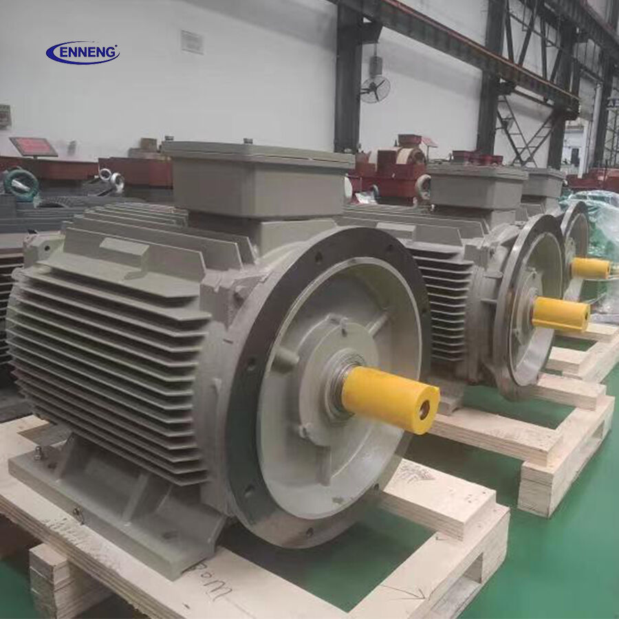
Induction machines require continuous electrical current circulation within rotor aluminum or copper bars to establish torque-producing magnetic fields. These currents generate continuous internal Joule heating (I2R losses), raising core temperatures and stressing mechanical bearings. An advanced PM Synchronous Motor utilizes rare-earth permanent magnets to establish synchronous rotor flux without electrical current flow. Removing rotor losses lowers operating temperatures by 15 to 30 degrees Celsius, preserving winding insulation integrity and extending lubricant operational life in high-temperature ambient conditions.
Industrial equipment such as crushers, extruders, and agitators rarely operate at steady nameplate capacity. Continuous process variations force drives to operate between 30 and 70 percent load for extended periods. When standard induction motors operate below half load, electrical efficiency collapses dramatically, wasting vast quantities of energy. A PM Synchronous Motor exhibits an exceptionally flat efficiency curve, sustaining peak energy conversion efficiency from 25 percent to beyond 110 percent load. This sustained performance yields massive financial savings across variable-load production cycles.
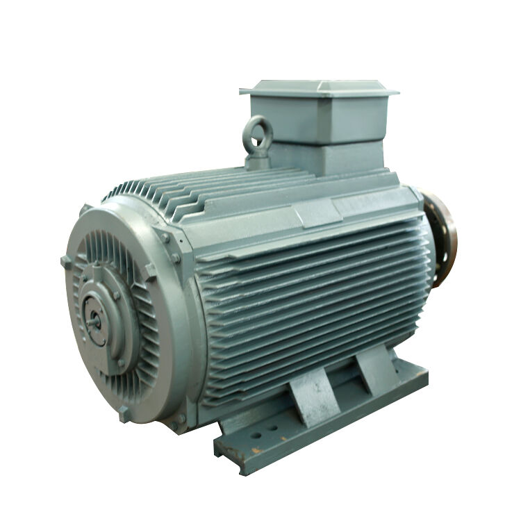
Harsh industrial airborne particulates rapidly destroy external mechanical transmission systems. Drive belts slip and snap under abrasive grit, while gearbox seals fail, allowing caustic slurries to contaminate gear lubricants. Implementing a low-speed, high-torque PM Synchronous Motor enables direct coupling to driven shafts, eliminating intermediate gear reducers, pulleys, fluid couplings, and belt guards. Removing intermediate mechanical linkages eradicates primary failure points and eliminates recurring oil changes.
Meeting severe industrial operating challenges requires robust electrical machinery designed for maximum physical endurance and electrical efficiency. ENNENG manufactures heavy-duty direct-drive permanent magnet synchronous drive systems engineered to reduce total cost of ownership across rigorous industrial applications. Upgrading industrial drivetrains with an ENNENG PM Synchronous Motor cuts active electrical power consumption by 10 to 40 percent compared to conventional induction platforms.
|
Operating Characteristic |
Standard Industrial Induction Motor |
ENNENG PM Synchronous Motor |
|
Operating Voltage Envelope |
380V — 440V Rigid |
110V to 690V Unified Versatility |
|
Power Capability Range |
Modular Limited Frames |
5kW to 5MW Unified Platform |
|
Temperature Rise Rating |
Class B (80K) |
Lower than 60K |
|
Operating Power Factor |
0.80 — 0.86 Average |
0.96 — 0.99 Near-Unity |
ENNENG synchronous equipment covers broad industrial capacities from 5kW up to 5MW multi-megawatt systems, with complete voltage versatility ranging from 110V to 690V. Operating with an internal temperature rise below 60K ensures prolonged mechanical and electrical integrity under severe ambient conditions.
ENNENG motors feature heavy-duty cast iron or fabricated steel carcasses with ingress protection ratings ranging from IP55 to IP68. Specialized multi-coat epoxy surface treatments protect structural housings from corrosive chemical acids, caustic alkalis, and saline mists. Advanced labyrinths and contact shaft seals prevent particulate ingress, keeping high-performance bearing cavities pristine.
Standard induction motors draw significant inductive reactive current from plant electrical distribution networks, depressing factory power factors below 0.85 and triggering severe monthly utility penalty charges. An ENNENG PM Synchronous Motor operates at power factors between 0.96 and 0.99 across normal working speeds. Eliminating reactive current draw unburdens plant step-down transformers, reduces distribution cable losses, and eliminates the capital cost of external power factor correction capacitors.
Industrial total cost of ownership calculations and machine reliability metrics must conform to international engineering standards. Motor electrical efficiency testing and classification are governed by IEC 60034-30-1 and IEC 60034-2-1, establishing super-premium IE4 and ultra-premium IE5 performance categories.
Field mechanical vibration severity limits must comply with ISO 10816-3 and ISO 20816-3, mandating that rigid-mounted machinery operate below 1.4 mm/s RMS for long-term mechanical reliability. Operating a balanced PM Synchronous Motor ensures compliance with stringent Zone A vibration thresholds. Furthermore, electrical installation design must satisfy NFPA 70 National Electrical Code standards, while occupational noise abatement in motor control rooms must adhere to OSHA 1910.95 regulations. For industrial asset management, implementing life-cycle costing following ISO 15663 protocols guarantees transparent, audited capital allocation decisions.
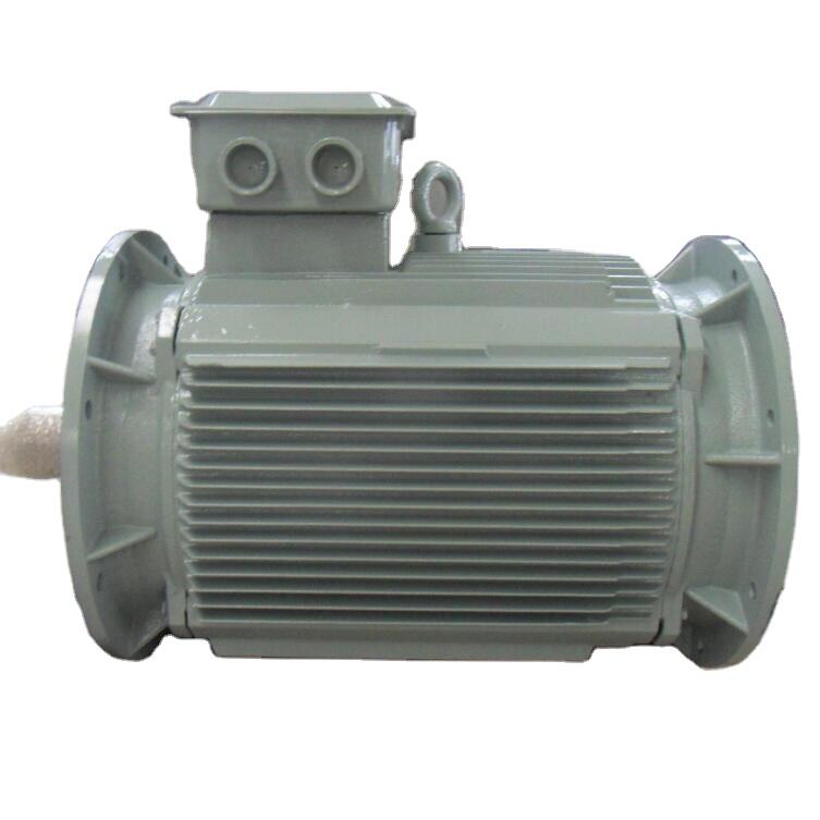
Securing the lowest lifecycle cost requires methodical equipment selection and disciplined preventative maintenance practices.
Before motor procurement, deploy three-phase power quality analyzers on existing motor feeder circuits to capture continuous kilowatt demand, peak starting currents, and process idle durations over full operating weeks. Select a PM Synchronous Motor sized to actual operating shaft load rather than oversized legacy nameplate ratings. Sizing motors accurately optimizes inverter capacity and captures maximum partial-load electrical efficiency.
Because permanent magnet synchronous drives operate with variable frequency inverters, ensure motor supply circuits utilize symmetrical, shielded inverter-duty cables conforming to IEC 61800-3 EMC standards. Install insulated non-drive-end bearings and conductive shaft grounding rings to dissipate high-frequency capacitive common-mode currents, preventing electrical discharge machining (EDM) fluting across bearing raceways.
Take advantage of direct-drive simplicity by establishing condition-based surveillance schedules. Monitor bearing vibration spectra every quarter to identify mechanical imbalance or early race fatigue. Perform annual winding insulation resistance tests using a 1000V DC megohmmeter. Because direct-drive motors eliminate gear reducers and belts, technicians avoid messy oil flushes and belt re-tensioning, focusing maintenance hours on core production assets.
To review complete permanent magnet motor lines, explore the ENNENG Products Catalog and review systems via ENNENG Drive Technologies.
For engineering evaluations regarding synchronous motor retrofits and total cost of ownership modeling, contact ENNENG:
Q: Why does a PM Synchronous Motor deliver lower total cost of ownership than an induction motor?
A: Although initial purchase costs are slightly higher, an advanced PM Synchronous Motor lowers continuous electrical consumption by 10 to 40 percent through rotor loss elimination. Furthermore, gearless direct-drive architecture eliminates gearboxes, pulleys, and continuous oil changes, reducing maintenance overhead and preventing expensive unscheduled line downtime over decades of service.
Q: How does a PM Synchronous Motor survive abrasive particulate environments?
A: High-durability synchronous motors utilize totally enclosed casings conforming to IP55, IP65, or IP68 standards. Heavy-duty cast housings, sealed bearing isolators, and chemical-resistant epoxy coatings isolate critical internal stator laminations and rare-earth magnets from airborne contaminants. Internal vacuum pressure impregnation prevents dust buildup from degrading winding dielectric strength.
Q: Can an existing induction motor drive be reused with a PM Synchronous Motor?
A: Standard scalar V/Hz induction motor drives cannot control permanent magnet synchronous equipment safely. A PM Synchronous Motor requires an inverter equipped with permanent magnet field-oriented vector control algorithms or active rotor position tracking. Modern universal drives feature selectable software firmware that seamlessly switches to permanent magnet motor control modes.


 EN