
 EN

Walk onto a tire compounding floor when a cold bale of natural rubber drops into an internal mixer, or watch the ammeter on a jaw crusher when wet rock hits the chamber. The shaft demands an immediate torque spike before material starts to shear. On legacy drivetrains built around induction motors and gearboxes, those first three seconds are where equipment fails. Rotor slip spikes, current shoots past breaker limits, rotor bars bake under induced heat, and gear teeth take a brutal hammer blow.
ENNENG builds permanent magnet rotating machines engineered for these rough duty cycles, covering a unified 5kW-5MW power range and 110V-690V voltage range alongside 1kW-10kW vertical axis wind turbine generators (3kW, 5kW, and 10kW units). Switching to a PM Synchronous Motor changes how the machine handles shock loads, provided the package is sized around the real surge profile rather than a catalog kilowatt number. Instead of relying on induced rotor current that lags the load, an NdFeB (Neodymium Iron Boron) rotor brings its own magnetic field to the shaft from zero RPM.
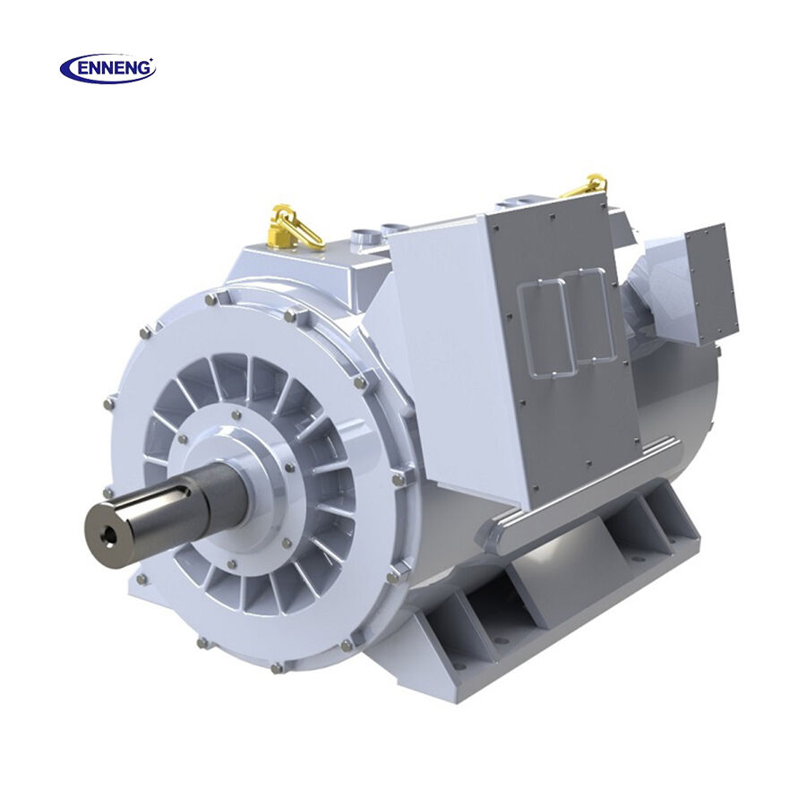
What Happens Inside the Motor During a Load Spike
When a mining conveyor restarts under ore or a slurry pump clears a plugged line, the load step travels straight to the air gap.
No Rotor Slip Means Instant Torque Stiffness
An asynchronous induction motor faces a catch-22 during a surge: to make extra torque, the rotor must slow down relative to the stator field so more current can be induced across the air gap. If a load spike pushes the rotor past its breakdown slip point, torque collapses and the drive stalls. A PM Synchronous Motor works on a locked magnetic coupling where rotor poles track stator frequency without slip. When the Variable Frequency Drive (VFD) senses a sudden torque step, vector control injects current along the torque axis in milliseconds. Combine permanent-magnet flux with rotor reluctance design, and a Permanent Magnet Motor PMSM delivers high pull-out torque right when a crusher or mixer needs to muscle through a jam.
Starting the Surge 20K Cooler Makes All the Difference
Overload capability is a heat-storage problem. A motor running near its thermal ceiling during normal shifts has almost zero room to absorb a 160% current spike without cooking stator varnish or pushing magnets toward demagnetization. Because a PM Synchronous Motor carries pre-magnetized NdFeB poles, zero excitation current flows in the rotor and rotor copper loss disappears. In daily operation, an ENNENG High Torque Permanent Magnet Motor runs with a temperature rise 20K lower than an induction motor—staying under 60K on continuous shifts. That 20K cooler baseline acts as a thermal cushion when repeated S3 or S6 cyclic surges hit under IEC 60034-1 duty rules.
|
Field Operating Factor |
ENNENG PM Synchronous Motor (PMSM) |
Standard Induction + Gearbox |
|
Shaft Under Shock |
Locked synchronous speed; fast vector torque |
Rotor slip rises; speed droops |
|
Baseline Winding Temp |
Zero rotor copper loss; 20K cooler (<60K) |
High rotor heat cuts margin |
|
Efficiency Plateau |
IE5 (IEC 60034-30-1); 25%-120% load (+2%-5%) |
Drops below 50% load |
|
Power Factor & Amps |
0.95 to 1.0; >10% lower amps frees VFD |
Peaks near 0.86; trips drives |
|
Power & Voltage |
5kW-5MW / 110V-690V (Wind: 1kW-10kW; 3kW, 5kW, 10kW) |
High-speed frames + reducers |
Shop-Floor Checks That Make or Break Surge Performance
Buying a Permanent Magnet Motor PMSM on nameplate kilowatts alone is a trap. A 200 kW motor at 1500 RPM and a 200 kW unit at 60 RPM deliver vastly different shaft torque.
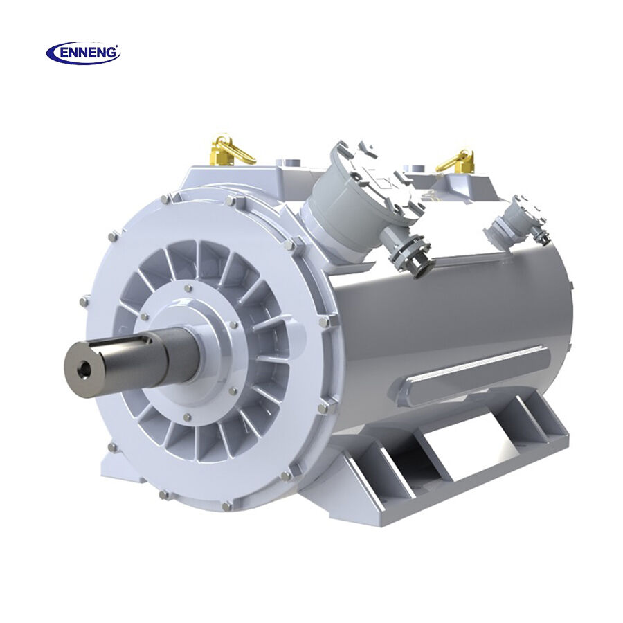
Size for Pull-Out Torque and Ditch the Gearbox Where Possible
Every intermediate gearbox, fluid coupling, or belt set adds backlash and torsional wind-up during a load step. When a jam clears, stored spring energy snaps back into the pinion teeth. By increasing rotor pole counts, ENNENG builds each Industrial Direct Drive Motor and PM Synchronous Motor to run at single-digit rated speeds, coupling straight to the load shaft. Removing the reducer eliminates gear-tooth fatigue, oil leaks, and OSHA 1910.219 guarding work while keeping noise under 55 dB and vibration within ISO 10816 and ISO 20816 limits. In Linglong Tire mixing lines, direct-drive retrofits cut power bills by 7% to 40%, while variable-demand air compressors at Sinopec and Shandong Gold Mine cut electricity use by up to 50%.
Match the VFD Current Ceiling and Winding Insulation
A PM Synchronous Motor only pulls as hard as its inverter allows. If the motor handles 200% peak torque but the VFD has a 110% current limit, the drive trips the moment a surge hits. Integrators must match the inverter's overload rating to the worst-case torque step. Because a Permanent Magnet Motor PMSM runs at a 0.95 to 1.0 power factor across 25% to 120% load, baseline current is over 10% lower than an induction unit, keeping cable and VFD heat down. Stator coils must also meet ANSI/NEMA MG 1 Part 31 voltage-spike rules and NFPA 70 grounding codes.
Specifying a Surge-Ready Motor Without Guessing
Backed by engineers from the National Rare Earth Permanent Magnet Engineering Centre and dozens of patents, ENNENG builds custom PM Synchronous Motor and Permanent Magnet Motor PMSM packages across 110V-690V (380V/660V/1140V) and 6kV/10kV frames—one to two frame sizes smaller than induction units. Before releasing a build sheet, project leads should lock down three details:
• Map the Surge Cycle: Record continuous torque, peak shock torque, surge seconds, and hourly frequency.
• Coordinate Drive Sensors: Tie PT100 probes and encoders into VFD logic to trim load safely.
• Maintain Field Care: Grease insulated bearings, clear dust from fins to hold <60K temperature rise, and check alignment.
Talk with ENNENG Engineering
Reach out to the ENNENG engineering support team with load-surge curves to get a tailored PM Synchronous Motor build sheet:
- WhatsApp: +86 18562780228
- E-Mail: [email protected]
- Phone: +86 532 66000559
FAQ
Q: Why does a PM Synchronous Motor handle sudden industrial load surges without stalling like an induction motor?
A: An induction motor relies on rotor slip to induce current, meaning heavy shock loads cause speed droop and rapid rotor heating. A PM Synchronous Motor uses permanent NdFeB rotor magnets locked synchronously to the stator field. Paired with VFD vector control, it delivers immediate pull-out torque across 25% to 120% load while running 20K cooler than induction designs.
Q: How does removing the gearbox with a Permanent Magnet Motor PMSM protect equipment during shock loads?
A: High-pole-count design allows an ENNENG Permanent Magnet Motor PMSM to couple straight to low-speed driven shafts without an intermediate speed reducer. Removing the mechanical gearbox eliminates backlash, pinion tooth shear, and oil seal failures during abrupt torque spikes while keeping vibration within ISO 20816 limits and operating noise below 55 dB.
Q: What power and voltage options can ENNENG build for heavy-duty surge applications?
A: ENNENG builds custom PM Synchronous Motor and generator packages across a unified 5kW-5MW power range and 110V-690V voltage range, plus 1kW-10kW vertical axis wind turbine generators focused on 3kW, 5kW, and 10kW models. Frame sizes, shaft geometry, and ANSI/NEMA MG 1 Part 31 inverter-duty windings are tailored to exact plant surge profiles.

