
why-pm-synchronous-motor-shows-better-comprehensive-performance-under-partialload-industrial-working-states, why-pm-synchronous-motor-shows-better-comprehensive-performance-under-partialload-industrial-working-states, /blog
EN

2026/10/10
Continuous manufacturing environments frequently expose electric drivetrains to dynamic cycle variations where equipment operates far below nameplate capacity. In chemical processing plants, municipal water treatment facilities, and automated conveyance hubs, motor loads fluctuate between 25% and 60% of rated capacity for more than two-thirds of annual operating hours. Under these variable duty conditions, deploying a conventional induction drive often results in severe electrical penalties, whereas a modern PM Synchronous Motor maintains an exceptionally flat efficiency curve that preserves electrical energy and stabilizes plant operations.
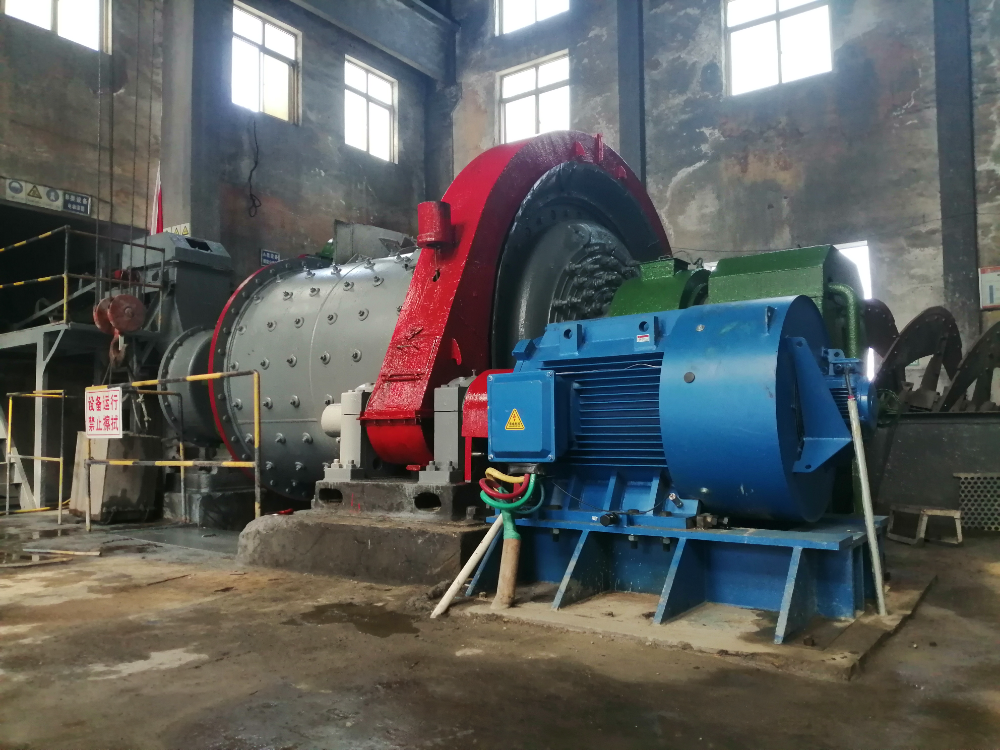
Continuous fluid transport networks in petrochemical refineries and municipal wastewater treatment plants routinely subject electric drivetrains to variable process throughput. Pumping stations designed with generous safety margins spend over 65% of annual operating hours operating between 25% and 60% of continuous nominal output. Under these throttled conditions, centrifugal impellers demand reduced shaft torque while motor rotational speeds fluctuate based on process feedback loops.
Running standard squirrel-cage induction drives under fractional loading produces severe electrical degradation. Because asynchronous motors depend on stator-drawn magnetizing currents to induce rotor flux, the reactive current component remains virtually constant regardless of shaft load. Consequently, when active mechanical shaft load drops to 30%, operating power factor collapses from a full-load 0.86 down to below 0.50. Plant electrical distribution substations suffer elevated kVA demands, harmonic distortions, and low power factor utility fines. Simultaneously, induced rotor currents continue producing internal I²R resistance losses, heating bearings and accelerating insulation aging. To resolve these operational penalties, ENNENG supplies high-efficiency industrial PM Synchronous Motor solutions across the 5kW to 5MW power spectrum and 110V to 690V operating ranges, eliminating rotor copper losses and maintaining operational stability across the entire power curve.
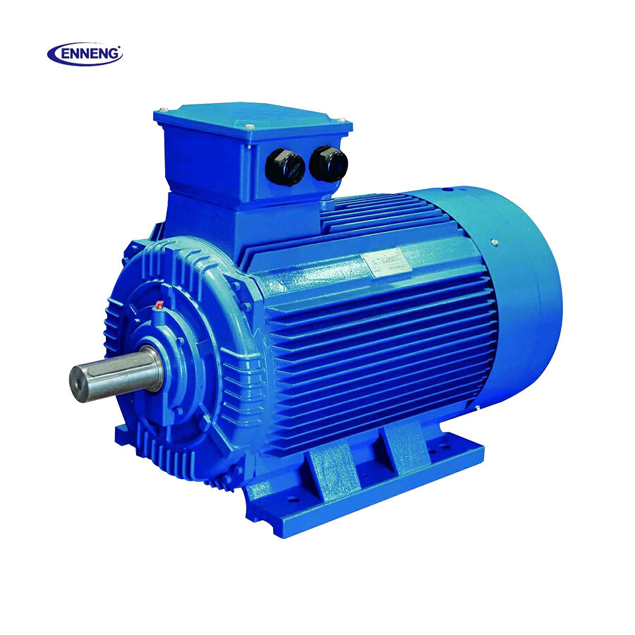
The superior partial-load performance of a PM Synchronous Motor originates directly from rotor physics. Instead of drawing excitation energy across the stator air gap, a PM Synchronous Motor utilizes high-coercivity rare-earth permanent magnets embedded directly within the rotor core. Rotor flux is established permanently, eliminating excitation current draw from the main power line. Synchronous rotation eliminates rotor slip completely, meaning rotor copper losses are virtually zero across the entire speed and torque envelope. When production demand drops from 100% to 35% load, stator current in an ENNENG PM Synchronous Motor declines proportionally with torque demand, allowing efficiency to remain virtually flat down to 25% loading.
Quantitative Operating Data Across Varied Load Steps
Under dynamic industrial operation, an ENNENG 200kW PM Synchronous Motor running at 40% load consumes up to 14% less electrical power than an equivalent induction motor. The power factor remains above 0.92 even at 25% load, eliminating the necessity for supplemental power factor correction capacitor banks.
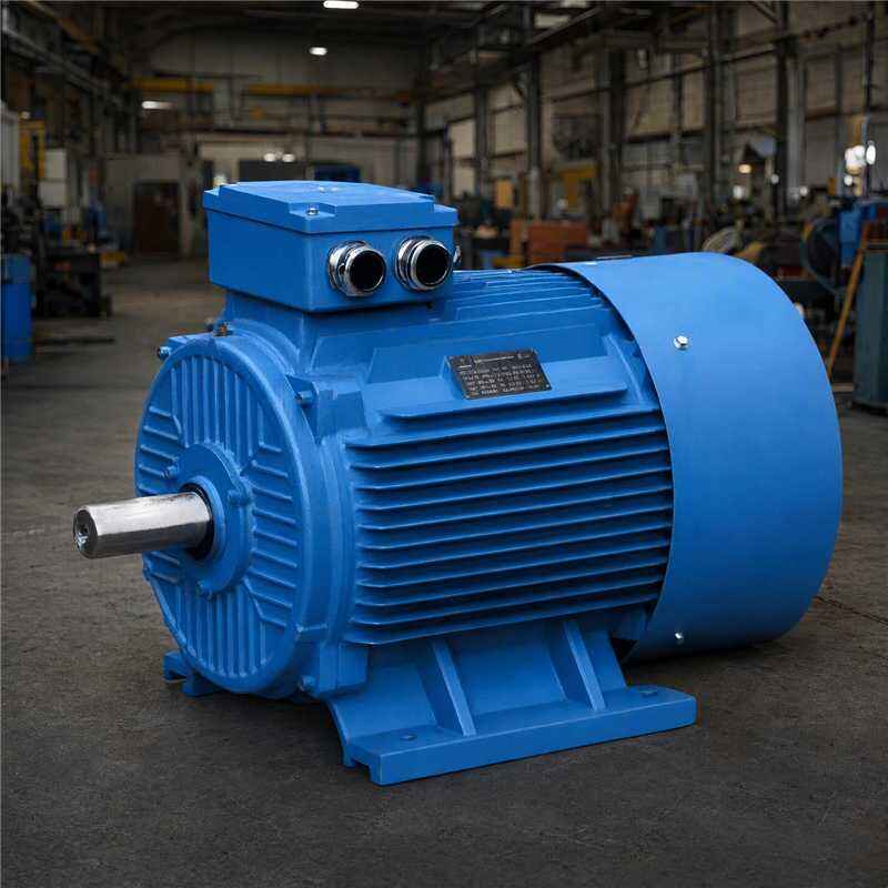
Efficiency compliance for variable-speed industrial drives is governed by international standard IEC 60034-30-2, which defines IE4 and IE5 performance criteria across partial-load and fractional-speed testing points. ENNENG PM Synchronous Motor models surpass IE5 ultra-premium benchmarks throughout 25% to 100% load bands. Facilities maintaining ISO 50001 energy management certification utilize these verified partial-load metrics to achieve documented carbon intensity reductions. In industrial installations subject to NFPA 70 Article 430 requirements, permanent magnet drivetrains provide reduced thermal loads inside control switchgear and compliant branch circuit protection.
Optimizing plant electrical infrastructure across fluctuating process cycles requires verified permanent magnet technology and matched inverter drive systems. Technical engineers at ENNENG assist industrial facilities in evaluating load duty profiles, conducting energy payback calculations, and configuring custom permanent magnet systems. Submit operating requirements to initiate a facility partial-load audit:
Q: Why does a PM Synchronous Motor maintain high efficiency at 25% load?
A: A PM Synchronous Motor maintains high partial-load efficiency because its excitation field is generated by permanent magnets rather than stator-induced current. Without rotor copper losses, the primary energy expenditure scales directly with the mechanical torque demanded by the driven machine. Consequently, core losses and thermal dissipation remain minimal, allowing the motor to sustain IE5 efficiency levels even during severely throttled light-load operation.
Q: What drive topology is required to operate a PM Synchronous Motor?
A: A PM Synchronous Motor cannot connect directly across standard line power; it requires an inverter equipped with field-oriented vector control. The variable frequency drive monitors rotor position via encoder feedback or sensorless high-frequency injection algorithms to synchronize output current with the permanent magnet field, ensuring smooth torque generation, accurate speed regulation, and maximum efficiency across wide partial-load operating ranges.
Q: How does thermal management differ between induction motors and a PM Synchronous Motor?
A: In standard induction machinery, rotor resistance creates significant internal heat that passes through bearings and shafts. In a PM Synchronous Motor, the rotor remains cool because no slip currents exist, reducing thermal stress on mechanical bearings. Heat is concentrated almost entirely in the stator housing, where external cooling fins and forced ventilation dissipate thermal energy efficiently during continuous industrial service.


 EN