
 EN

When a factory reviews fan energy use, the conversation often stops at motor efficiency. That misses a second electrical-system question: how much current must the supply deliver to support the work? PMSM for Industrial Fans can improve this picture because a permanent magnet synchronous motor does not need rotor magnetizing current in the same way as an induction motor. But the useful answer is more precise than “PMSM equals better power factor.” The factory sees the combined behavior of the motor, variable frequency drive (VFD), control settings, fan duty cycle, and harmonic environment.
For an engineer comparing a Permanent Magnet Motor PMSM package with an induction-fan package, the practical objective is not a nameplate claim. It is lower unnecessary current, stable fan control, and a measured improvement in the facility’s real operating conditions.
Start with what power factor changes in a fan system
Power factor describes how effectively apparent power is converted into useful real power. In a conventional AC motor system, reactive power supports the magnetic fields needed for torque production. It occupies capacity in transformers, cables, switchgear, and generators even though it does not directly turn the fan. A lower power factor therefore raises current for a given kW demand, increasing conductor losses and consuming distribution capacity.
An induction motor creates its rotor field through magnetizing current. A PMSM for Industrial Fans uses permanent magnets on the rotor, so it can reduce the magnetizing component at the motor terminals. With appropriate current control, the stator current can be aligned more closely with the torque-producing axis. That is the electrical mechanism behind the power-factor opportunity.
There is an important boundary: the power factor at the motor terminals is not automatically the power factor at the factory incomer. If the fan is VFD-driven, the drive input rectifier, DC link, line reactor, passive or active harmonic filtering, and the rest of the plant load all influence the number that the utility meter sees.
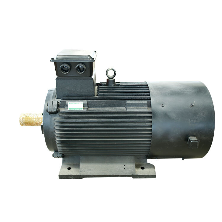
Why the benefit is often meaningful for industrial fans
Fans are strong candidates because airflow demand is frequently variable. Instead of throttling dampers while a motor runs at constant speed, a VFD can reduce fan speed to match ventilation, cooling, or process demand. Fan affinity laws indicate that flow changes roughly with speed, pressure changes roughly with the square of speed, and shaft power changes roughly with the cube of speed. A modest speed reduction can therefore reduce real-power demand substantially.
That lower-load operating range is where motor selection matters. Permanent magnet machines can maintain favorable efficiency and controllability across a broad speed range when the motor and VFD are correctly matched. A PMSM for Industrial Fans can therefore reduce both kW consumption and the reactive-current burden associated with an induction motor. The two benefits are related but different: lower kW does not prove better power factor, and better power factor does not by itself prove lower kWh.
Motor power factor versus drive input power factor
This distinction prevents many disappointing retrofit expectations. On the output side, the VFD supplies a controlled waveform to the Permanent Magnet Motor PMSM. On the input side, a standard six-pulse rectifier can draw non-sinusoidal current. Displacement power factor may be high, while true power factor is reduced by current harmonic distortion.
For that reason, a factory should review at least four values before and after a retrofit:
- Real power (kW): the useful electrical power consumed by the fan system.
- Reactive power (kVAr): the portion associated with magnetic-field support and other reactive effects.
- Apparent power (kVA): the loading imposed on supply equipment.
- True power factor and current THD: measured at the VFD input or at the relevant distribution board.
If the factory has capacitor banks, their controller also needs review. A VFD-rich system may require detuned reactors, harmonic filters, or an active front end depending on measurements and the facility’s power-quality limits. Adding capacitors without checking resonance and harmonics is not a safe substitute for a proper drive-input assessment.
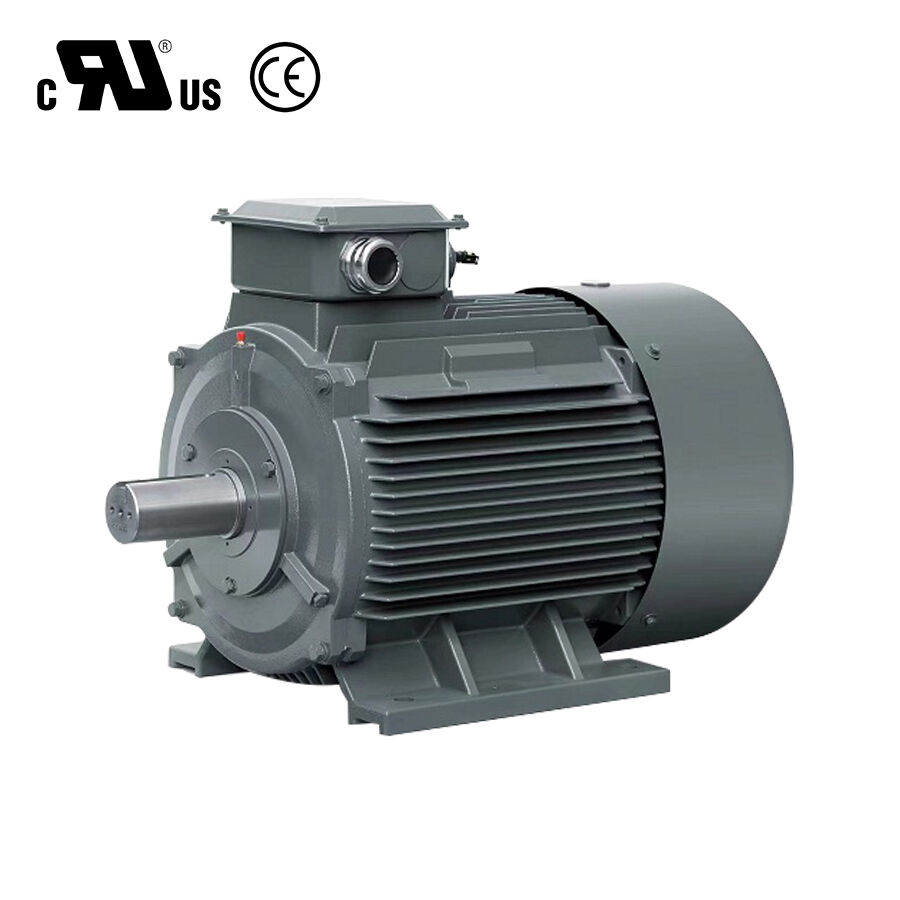
Where a PMSM fan retrofit can improve factory capacity
Consider a ventilation bank that cycles through low, medium, and high demand. With an induction motor, damper control, and poor part-load conditions, the system may draw more current than the air requirement justifies. Replacing the control strategy with a VFD-driven PMSM for Industrial Fans lets the system reduce speed when the process permits. The lower torque demand reduces kW, while the motor’s excitation characteristics can reduce the reactive component on the motor side.
The result can be useful capacity relief in upstream equipment. Lower current reduces I²R losses in feeders and may help avoid transformer or generator loading that is driven by kVA rather than kW alone. Still, the benefit must be calculated from measured intervals, not inferred from rated motor data. Fan curve, static pressure, duct condition, operating hours, and the number of fans running all affect the result.
Five specification checks before selecting a PMSM fan package
- Map the real duty cycle. Log fan speed, pressure, airflow proxy, kW, and run hours. A fan that operates near one fixed point may not justify the same design choice as a fan with wide daily variation.
- Confirm VFD compatibility. The drive must support PMSM control, with commissioning parameters based on the motor data supplied by the manufacturer. Sensorless and encoder-based control have different startup and low-speed implications.
- Specify the measurement point. State whether the acceptance criterion is motor-side power factor, VFD input true power factor, the MCC feeder, or the facility incomer. These are not interchangeable values.
- Review harmonics and existing correction equipment. Measure current THD and inspect capacitor-bank switching, reactors, and transformer loading before finalizing a retrofit.
- Check the mechanical fan match. Torque-speed requirements, inertia, bearings, mounting, and airflow performance must suit the new operating envelope. A high-efficiency motor cannot correct an improperly selected fan or restrictive ductwork.
A practical verification plan
Ask the supplier or integrator to define a baseline and an acceptance test. Capture three representative operating points rather than a single full-speed snapshot. At each point, record voltage, current, kW, kVAr, kVA, true power factor, current THD, fan speed, and process condition. Compare equivalent airflow or pressure conditions, then review the data with the plant’s power-quality engineer.
For international projects, efficiency classes and test methods should be checked against the applicable market requirements. IEC TS 60034-30-2 provides a relevant variable-speed AC motor efficiency-class context, but it does not replace a site-specific electrical study. Similarly, a high efficiency classification does not guarantee that the drive input meets a particular utility power-factor or harmonic limit.
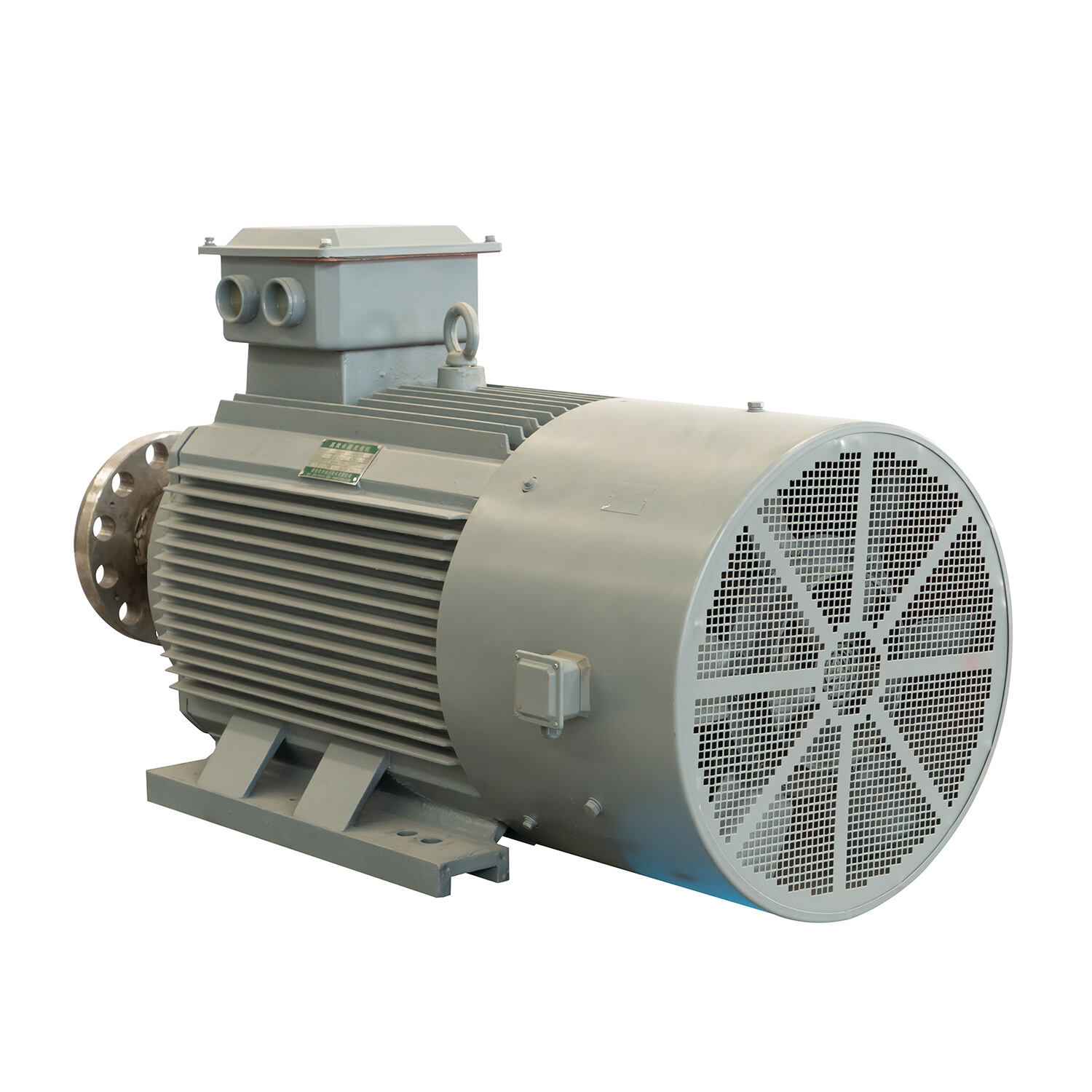
When PMSM is not the only answer
A PMSM for Industrial Fans is not automatically the right upgrade for every fan. If a fan runs continuously at a stable operating point, an appropriately sized high-efficiency induction motor may be a simpler economic option. If the distribution system’s primary issue is harmonic distortion from numerous existing drives, improving one motor’s output-side behavior will not solve the facility-level issue alone.
If you are evaluating commercial permanent magnet motors for sale and need an engineered drive solution that guarantees efficiency and longevity, ENNENG is your trusted partner.Contact ENNENG Today.Speak to our technical engineering team to receive a customised drive proposal.
- WhatsApp: +86 18562780228
- E-Mail: [email protected]
- Phone: +86 532 66000559

