
 EN

Continuous chemical processing plants operating variable-speed centrifugal transfer pumps 8,400 hours annually often experience sudden motor insulation burnouts and unexplained drive fault trips following routine plant expansions. Operating engineers discovering these electrical breakdowns frequently identify that long distribution feeder runs between remote variable frequency drive panels and pump stations create destructive standing waves. Ensuring continuous production uptime requires pairing every VFD compatible motor with a carefully matched cable topology, low-impedance grounding scheme, and appropriate output filtering rather than treating cabling as an afterthought.
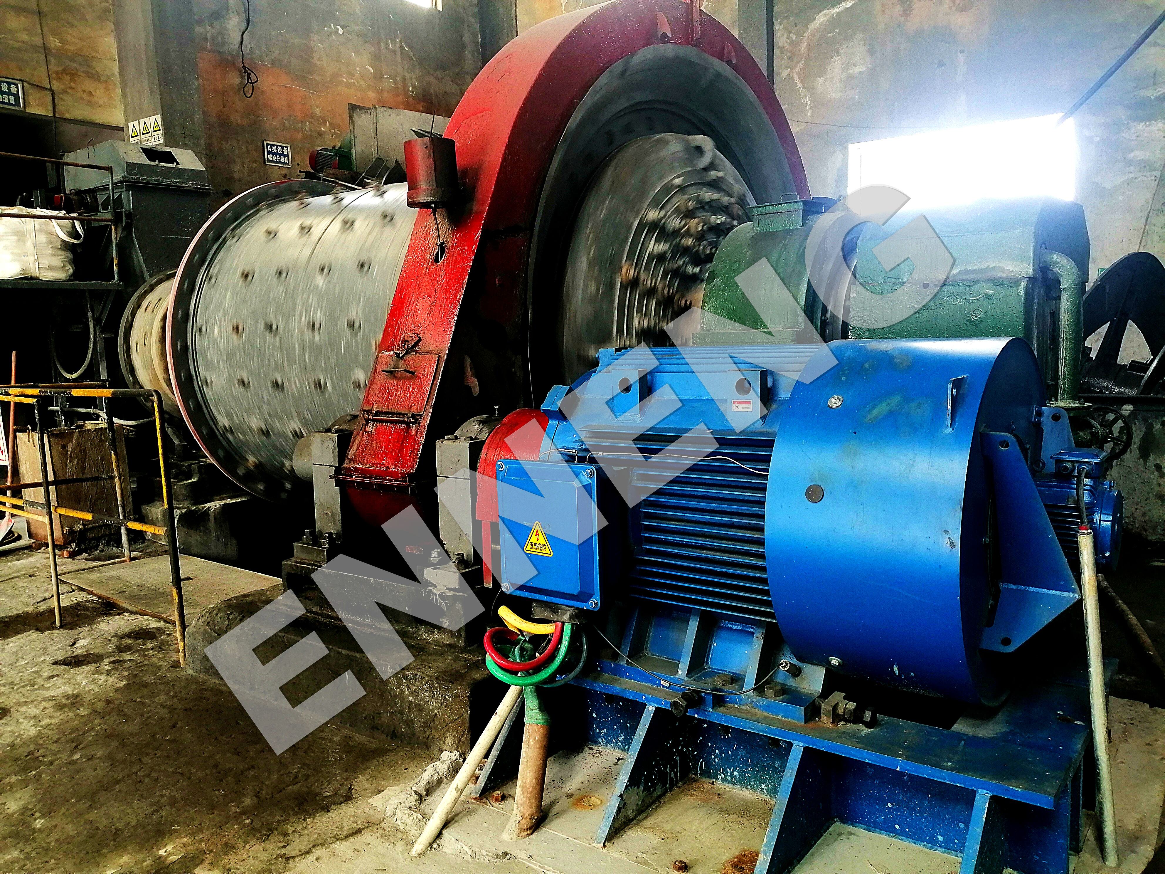
High-frequency voltage pulses delivered by pulse-width-modulated inverters interact with long, unmatched transmission cables to produce destructive voltage doubling and severe electromagnetic radiation. These electrical stresses degrade phase insulation barriers, induce destructive circulating bearing fluting currents, and compromise sensitive control instrumentation across congested industrial cable trays. ENNENG supplies advanced inverter-duty drive machinery and application engineering support to eliminate high-frequency transmission risks, delivering reliable operation across critical industrial manufacturing facilities.
Transmission Dynamics and Voltage Reflection Hazards on Site
Deploying a modern VFD compatible motor introduces high-frequency electromechanical interactions that do not occur in traditional grid-connected equipment. Modern variable frequency drives utilize insulated gate bipolar transistors that switch thousands of times per second with rapid voltage rise times (high dV/dt rates) often surpassing 5,000 to 10,000 volts per microsecond. A comprehensive energy saving motor solution must address how these steep pulse fronts propagate along plant cables to avoid premature dielectric breakdown.
Reflected-Wave Phenomenon and Insulation Dielectric Breakdown
When high-frequency drive output pulses travel down a distribution cable toward a VFD compatible motor, they encounter an impedance mismatch at the motor terminal junction box. A cable presents a characteristic surge impedance between 30 and 100 ohms, whereas an electric motor behaves as a high-impedance inductive load reaching several thousand ohms. This sharp discontinuity forces incident voltage waves to reflect back toward the inverter, superimposing upon succeeding incoming waves.
In installations with long cable runs exceeding thirty to fifty meters, this wave superposition creates transient voltage spikes approaching twice the nominal DC bus voltage. On a standard 480V or 690V industrial power bus, peak terminal voltages regularly exceed 1,600 to 2,200 volts. These severe transient spikes penetrate the first few turns of stator windings, sparking inter-turn partial discharge erosion and causing catastrophic phase-to-ground faults. Implementing a reinforced custom PM motor design equipped with inverter-grade magnet wire and void-free vacuum pressure impregnation provides the dielectric withstand capability necessary to endure continuous voltage reflections.
Common-Mode Currents, Capacitive Charging, and Bearing Fluting
In addition to differential-mode voltage spikes, the rapid switching dynamics of inverter-fed systems generate high-frequency common-mode voltages between stator winding phases and ground. This common-mode voltage couples capacitively through cable conductor shields, motor internal air gaps, and bearing oil films. In an unmatched cabling installation, continuous high-frequency common-mode currents seek the path of least resistance through the drive grounding bus and motor structural bearings.
When common-mode voltage across the bearing lubricant film surpasses the breakdown threshold, electrical discharge machining occurs. Microscopic electric arcs blast tiny craters into bearing raceways and rolling elements, resulting in premature bearing fluting, acoustic whining, severe vibration, and eventual mechanical seizure. Deploying an advanced PM synchronous motor requires symmetrical, shielded drive cables combined with internal shaft grounding rings and insulated non-drive end bearings to safely divert parasitic currents away from mechanical bearing assemblies.
Electromechanical Parameters and Cable Architecture Selection
Selecting an appropriate cable for a VFD compatible motor requires examining physical cable construction, shield geometry, dielectric insulation materials, and secondary protective filtering. Standard commercial building wire or unshielded tray cables lack the physical shielding and dielectric endurance required for pulse-width-modulated drive circuits.
Symmetrical Shielded Cable Geometry and Low-Impedance Grounding
Proper cable geometry plays a decisive role in suppressing circulating ground currents and electromagnetic interference. Standard unshielded power cables or four-conductor cables featuring a single ground conductor create asymmetrical magnetic fields that induce high common-mode ground currents into surrounding instrumentation trays. A dedicated VFD compatible motor installation requires symmetrical shielded inverter cables containing three phase conductors and three segmented ground conductors positioned symmetrically within conductor interstices.
Continuous dual-layer shielding, incorporating both heavy-gauge braided tinned copper and overlapping aluminum-mylar tape, provides superior high-frequency attenuation. Terminating these shields using 360-degree brass EMC cable glands at both the drive enclosure and the motor terminal box ensures a low-impedance return path for common-mode currents. This rigorous containment prevents high-frequency electromagnetic noise from corrupting nearby programmable logic controller networks and process sensor lines.
|
Cable Architecture Metric |
Standard Commercial Building Cable |
Industrial Symmetrical VFD Cable |
|
Conductor & Ground Configuration |
3 Phase Conductors + 1 Single Ground |
3 Phase Conductors + 3 Interstitial Symmetrical Grounds |
|
High-Frequency Shielding System |
None or thin foil tape only |
Dual-layer: 100% foil wrap plus ≥85% tinned copper braid |
|
Insulation Dielectric Material |
Standard PVC or generic cross-linked poly |
High-dielectric XLPE (low capacitive charging) |
|
Reflected-Wave Peak Tolerance |
< 1,000 Volts peak rating |
≥ 2,000 Volts peak inverter surge withstand |
|
Unified Operating Voltage Scope |
Standard 380V to 480V limits |
Unified 110V to 690V industrial capability |
|
Unified Motor Output Scope |
Limited commercial capacities |
Unified 5kW to 5MW industrial drive range |
|
Bearing Current Mitigation |
Uncontrolled common-mode loops |
Low-impedance 360-degree ground return path |
Mitigation Configurations: Output Reactors, dV/dt Filters, and Sine-Wave Filters
When layout constraints demand long cable routing between electrical substations and driven machinery, auxiliary output filtering becomes necessary to protect the VFD compatible motor. Adding an AC line output reactor introduces inductive impedance that dampens voltage rise times and restricts capacitive charging currents over moderate distances.
For cable lengths exceeding seventy-five to one hundred meters, installing a low-pass dV/dt filter attenuates voltage rise times below 200 volts per microsecond, capping peak terminal reflections within safe operating margins. In extreme installations spanning several hundred meters, such as deep-well submersible pumps or remote mining slurry lines, a full sine-wave filter transforms pulse-width-modulated square waves into smooth sinusoidal voltage curves. ENNENG motor products are engineered across unified voltage ratings from 110V to 690V and power outputs from 5kW to 5MW, providing exceptional dielectric resistance and mechanical integrity for variable-frequency operations. For off-grid plant power generation and remote monitoring facilities, ENNENG also delivers vertical axis wind turbine systems rated from 1kW to 10kW, emphasizing 3kW, 5kW, and 10kW platforms to ensure reliable utility supply.
Engineering Standards, Electrical Codes, and Site Maintenance Routines
Industrial drive installations must comply with strict international engineering standards and workplace electrical codes. Insulation coordination must satisfy IEC 60034-18-41 guidelines for qualification and type testing of converter-fed winding insulation. Motor terminal withstand limits should align with NEMA MG-1 Part 31 specifications for inverter-duty electrical machinery. Integrating an advanced Permanent Magnet Motor PMSM within plant energy management programs supports verified carbon reductions under ISO 50001 energy frameworks.
Long-term reliability demands structured preventive inspection protocols. Electrical technicians should perform high-frequency earth clamp testing to monitor ground circulating currents and conduct baseline insulation resistance measurements per IEEE 43 guidelines. Periodic thermal imaging across terminal lugs identifies high-resistance contact points caused by mechanical vibration or thermal cycling. Technicians must also inspect EMC gland terminations annually, verifying that shield clamping surfaces remain clean, tight, and free of corrosion.
Technical Support and Industrial Cable Integration Inquiries
Achieving optimal performance with a VFD compatible motor requires analyzing full-system interactions between inverter pulse switching, cable impedance characteristics, and driven load curves. Modernizing production assets with an advanced VFD compatible motor reduces electrical energy waste, prevents premature insulation breakdown, and protects mechanical reliability across continuous processing machinery. Application engineers provide complete high-frequency system modeling, cable matching calculations, and turnkey drive selection support. Contact the technical team today to evaluate site cabling parameters and specify customized motor systems.
- WhatsApp: +86 18562780228
- E-Mail: [email protected]
- Phone: +86 532 66000559
FAQ
Q: Why does cable length amplify voltage reflection stress in a VFD compatible motor?
A: When pulse-width-modulated inverter pulses travel along a cable, they encounter an impedance mismatch at the motor terminals. On extended cable runs, the transit time of the pulse front exceeds half the pulse rise time. This time lag allows reflected voltage waves to superimpose upon incoming waves, doubling terminal voltage spikes and severely stressing winding insulation.
Q: What cable construction best mitigates electromagnetic interference and bearing currents?
A: A symmetrical shielded VFD cable featuring three active phase conductors and three interspersed, segmented ground wires provides superior electromagnetic balance. Encasing this geometry within a dual-layer shield composed of aluminum-mylar tape and dense tinned copper braid provides a low-impedance ground return path. This configuration neutralizes common-mode ground voltages and protects nearby control instrumentation from electromagnetic noise.

