
why-pm-synchronous-motor-helps-cut-down-reactivepower-loss-inside-industrial-powerdistribution-loops, why-pm-synchronous-motor-helps-cut-down-reactivepower-loss-inside-industrial-powerdistribution-loops, /blog
EN

2026/09/20
Industrial distribution loops carry real current that does useful work and reactive current that only circulates between supply and load. Induction machines, transformers, and long cables draw magnetizing VAR that heats conductors and occupies transformer rating. ENNENG addresses this at the source with a PM Synchronous Motor that needs no excitation winding and holds near-unity power factor across its load range. For continuous fan and pump duty, the unit removes magnetizing VAR where it is created.
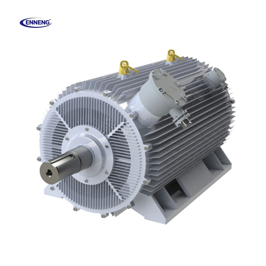
ENNENG's PM Synchronous Motor line is documented to eliminate reactive power penalties in variable-load duty, and the TYB series delivers 15%-30% energy savings while presenting a near-unity power factor. ENNENG's TYT series was deployed at Shandong Gold Group across its flotation line, ball mill, and bulk handling drives, where the same mounting dimensions as the incumbent asynchronous motors let existing pulleys and couplings stay in service, a retrofit that removes magnetizing VAR at the load without re-engineering the surrounding drive.
Reactive current is not free even when no penalty applies. Every ampere of VAR travels through the same cables, busbars, and windings as the real power, and the resistive loss grows with the square of total current. A loop at 0.8 power factor carries about twenty-five percent more current than the same load at unity, so heating and voltage drop rise even when the meter does not flag it. ENNENG displaces that lagging VAR locally with a PM Synchronous Motor, keeping the loop closer to unity and recovering wasted capacity.
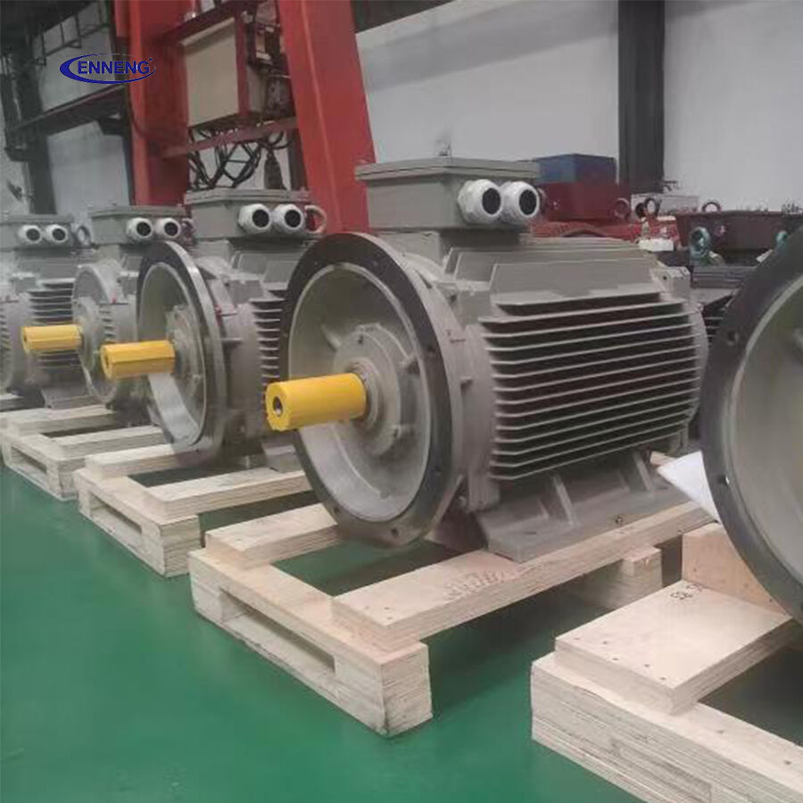
The physics is straightforward. A permanent-magnet rotor supplies its own field flux, so the PM Synchronous Motor draws almost no magnetizing current, and the drive sets the current angle so the unit presents leading, lagging, or unity power factor on demand.
Conventional machines need a field winding fed with DC excitation, and induction designs pull magnetizing current continuously. The PM Synchronous Motor removes the excitation path entirely: the magnets fix the rotor flux, and the stator current is used almost wholly for torque. With little magnetizing component, the line current aligns with the voltage, driving power factor toward unity and shrinking the VAR that would otherwise circulate in the loop. The contrast is clear under IEC 60034-1:
|
Aspect (IEC 60034-1) |
Induction Motor |
Permanent-Magnet Motor (IE5) |
|
Rotor excitation |
Field winding or magnetizing current |
Permanent magnets, no excitation current |
|
Rotor copper loss |
Present at every speed |
Zero across the speed range |
|
Power factor |
Lagging, draws VAR from grid |
Near-unity, can supply VAR locally |
|
Transformer load |
Higher total current |
Lower total current for same output |
ENNENG delivers this PM Synchronous Motor behavior with a vector-controlled drive so the benefit appears in the field, not only on the nameplate.
Loads rarely sit at a single point, and a fixed correction device cannot follow them. A PM Synchronous Motor with a vector-controlled drive holds a chosen power factor as the load moves from light to full, because the controller decouples torque current from magnetizing current, and where a loop is short of capacity it can be set slightly leading to supply VAR locally like a small synchronous condenser.
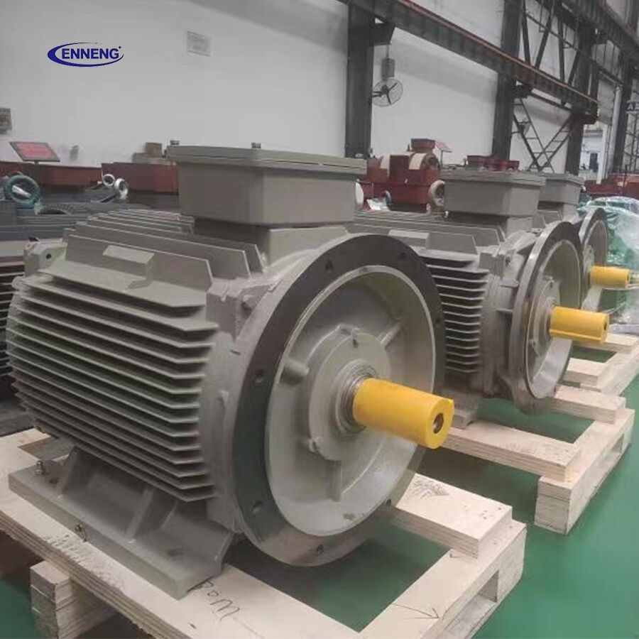
Credible claims rest on published references rather than marketing language. A PM Synchronous Motor is specified and tested against the same framework that governs rotating equipment, so its benefits are verified rather than asserted.
IEC 60034-1 sets the general performance and test requirements for rotating electrical machines, and IEC 60034-3 covers synchronous-machine-specific performance, giving a consistent basis to compare field-based designs with conventional excited machines and confirm the reactive draw reduction that a PM Synchronous Motor delivers.
IEEE 141, the Red Book, guides industrial power-distribution design and addresses power-factor correction, capacitor placement, and over-correction risk. IEC 61000 governs harmonic limits that any drive-fed PM Synchronous Motor must respect, keeping the plan within accepted practice and helping the site pass inspection.
Good results depend on choosing the right unit and keeping it healthy. A PM Synchronous Motor rewards careful specification because its power-factor benefit is only realized when the drive setpoint and the duty profile are matched to the loop. ENNENG supplies PM Synchronous Motor units — the ENNENG Permanent Magnet Motor (PMSM) line built to ISO 9001 and CE for exactly this duty.
Size the PM Synchronous Motor from the measured duty cycle, not the nameplate peak, and set the target power factor deliberately. If the loop is VAR-poor, program it slightly leading to offset lagging loads; if near unity, hold it at unity to avoid over-correction, and confirm the rating against IEC 60034-1 before purchase.
At commissioning, measure the line power factor and current on each phase with the PM Synchronous Motor loaded, and compare against the pre-change baseline to prove the VAR reduction. Check harmonic content against IEC 61000 and confirm the drive is not fighting an existing capacitor bank. Routine upkeep is light because the rotor has no slip rings or brushes, but periodic thermal and insulation checks protect the magnets and bearings, and re-verify the power factor yearly.
A power-factor upgrade should be sized from a measured duty profile, not a guess. ENNENG supplies PM Synchronous Motor units built to ISO 9001 and CE that hold near-unity power factor for plants in more than 20 countries.
Send ENNENG the one-week line power-factor and current log from the target loop, and the engineering team returns a VAR-reduction plan with a capacity-recovery estimate before purchase.
A: A PM Synchronous Motor carries its own rotor field from permanent magnets, so it draws almost no magnetizing current from the grid. The drive sets the current angle, letting the unit hold near-unity power factor. Less reactive current travels through cables and transformers, which lowers resistive losses and frees capacity that lagging loads would otherwise occupy in the distribution loop.
A: In many loops a PM Synchronous Motor reduces the need for switched capacitors because it generates reactive support right at the load. After replacing continuous drives, a site may retire one capacitor stage, as ENNENG's documented TYT deployments at sites such as Shandong Gold Group show. It is not a full substitute for bulk correction, but local VAR generation close to the load often removes the largest, most wasteful part of the reactive flow.
A: Yes, with a vector-controlled drive. A PM Synchronous Motor can hold a chosen power factor from light to full load because the controller separates torque current from magnetizing current. The setpoint follows the mechanical demand instead of drifting like a fixed capacitor. Operators can also choose a slightly leading setpoint to supply VAR locally when the distribution loop is short of reactive capacity.
A: IEC 60034-1 covers general rotating-machine performance and testing, while IEC 60034-3 addresses synchronous-machine specifics. For the distribution side, IEEE 141 guides power-factor correction practice and IEC 61000 sets harmonic and compatibility limits. These references let engineers verify rated losses and confirm that local VAR support stays within accepted, inspectable industrial power-distribution rules and accepted utility requirements.
A: Measure line power factor and per-phase current with the PM Synchronous Motor under load, then compare against the pre-change baseline to confirm the VAR drop. Check harmonic content against IEC 61000 and ensure the drive is not conflicting with an existing capacitor bank. Verify the set power-factor mode is active. Document the readings so later inspections can show the correction is still performing as specified.
A: Upkeep is lighter than for excited machines because the rotor has no slip rings, brushes, or field winding. Schedule periodic thermal imaging, insulation resistance checks, and bearing inspection to protect the magnets and mechanical parts. Re-verify the power-factor setting at least yearly as the load evolves, and keep the drive firmware current so the chosen power-factor mode and protective limits remain correctly applied.


 EN